Installing intake camshaft of cylinder bank 2
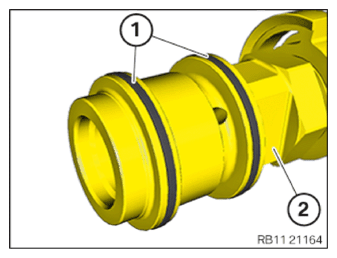
- Plastic rings (1) are maintenance free and do not need to be replaced.
- Check plastic rings for damage, replace if necessary.
NOTE:
TECHNICAL INFORMATION
The rocker arms may slip slightly when the camshaft is positioned. Make sure rocker arms are correctly positioned on the hydraulic valve clearance compensating elements and on valves.
The rocker arms may slip slightly when the camshaft is positioned. Make sure rocker arms are correctly positioned on the hydraulic valve clearance compensating elements and on valves.
- Position intake camshaft.
- When screwing the camshafts, make sure the valves have free movement.
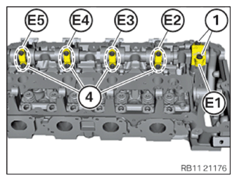
- Position guide bearing shells according to marks (E1) to (E5).
- Join the screws of the guide bearings with position numbers (1) and (4) in multiple steps by one half turn at a time until flush.
- Tighten the screws (1).
TIGHTENING TORQUES SPECIFICATION
| Intake/exhaust camshaft | ||
|---|---|---|
| M6 | Tightening torque | 10 Nm |
- Tighten down screws (4).
TIGHTENING TORQUES SPECIFICATION
| Intake/exhaust camshaft | ||
|---|---|---|
| M6 | Tightening torque | 10 Nm |
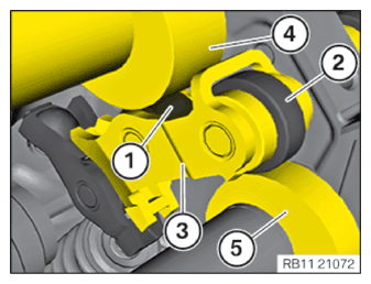
- All intermediate levers (3) must rest correctly on the idler pulley (1) and on the camshaft (4).
- All intermediate levers (3) must rest correctly on the idler pulley (2) and on the eccentric shaft (5).