Removing the intake plenum
WARNING:
High-voltage system.
The high-voltage system operates on the basis of hazardous, electrical voltage and high currents. Mortal hazard through electric shock!
The high-voltage system operates on the basis of hazardous, electrical voltage and high currents. Mortal hazard through electric shock!
- All work on the high-voltage system may only be carried out by specially trained and technically experienced personnel.
- For additional information see:
- For additional Information see:
WARNING:
Working on 12 V electrical system.
Risk of short circuits! Risk of fire!
Risk of short circuits! Risk of fire!
- Make sure that there is no charger connected to the jump start terminal in the engine compartment.
- Detach battery ground lead from battery.
- For auxiliary batteries: Detach battery minus cables from all auxiliary batteries.
NOTE:
RISK OF DAMAGE
Damage to battery terminal, the safety battery terminal or the intelligent battery sensor (IBS).
Damaged battery terminals can lead to malfunctions or vehicle electrical system faults.
Damage to battery terminal, the safety battery terminal or the intelligent battery sensor (IBS).
Damaged battery terminals can lead to malfunctions or vehicle electrical system faults.
- Detach battery terminal from battery pole by carefully shifting to and fro. Do not pry off using a tool.
NOTE:
TECHNICAL INFORMATION
Additional coolant can leakage. Make sure that no coolant enters the intake port of the cylinder head.
Additional coolant can leakage. Make sure that no coolant enters the intake port of the cylinder head.
NOTE:
TECHNICAL INFORMATION
Collect and dispose of emerging fluids. Observe country-specific waste disposal regulations.
Collect and dispose of emerging fluids. Observe country-specific waste disposal regulations.
Preliminary work
- Refer to BRINGING FRONT COMPARTMENT LID IN THE SERVICE POSITION .
- Refer to DISCONNECTING ALL BATTERY GROUND LEADS .
- Refer to REMOVING THE SEAL FOR THE HOOD REAR .
- Refer to REMOVING THE ACOUSTIC COVER .
- Refer to REMOVING ACOUSTIC COVER AT REAR .
- Refer to REMOVING THE DME CONTROL UNIT .
- Refer to REMOVING THE INTEGRATED POWER SUPPLY MODULE (PDM) .
- Refer to REMOVING CONTROL UNIT BRACKET .
- Refer to REMOVING RESONATOR .
- Refer to REMOVING THE FRONT UNDERBODY PROTECTION OR FRONT THRUST FIELD .
- Refer to REMOVING THE UNDERBODY PROTECTION OF THE STEERING GEAR AND THRUST FIELD RESPECTIVELY .
- Refer to DRAINING THE COOLANT FROM THE LOW-TEMPERATURE COOLING SYSTEM .
- Refer to CONNECTING THE COOLANT LINE OF LOW-TEMPERATURE COOLANT CIRCUIT .
- Refer to REMOVING TANK VENTING VALVE .
NOTE:
RISK OF DAMAGE
Damage to wires when disconnecting connectors and plug connections.
Sheared wires can cause a short circuit.
Damage to wires when disconnecting connectors and plug connections.
Sheared wires can cause a short circuit.
- Do not pull on wires when disconnecting connectors and plug connections.
NOTE:
TECHNICAL INFORMATION
Collect and dispose of emerging fluids. Observe country-specific waste disposal regulations.
Collect and dispose of emerging fluids. Observe country-specific waste disposal regulations.
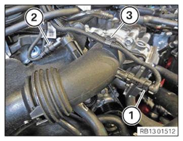
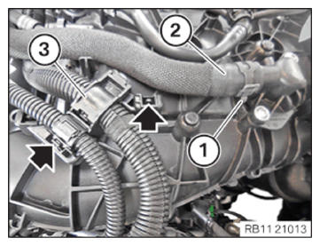
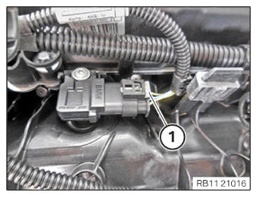
- Unlock plug connection (1) and disconnect.
- Unlock plug connection (2) and disconnect.
- Unlock and loosen clamp (3).
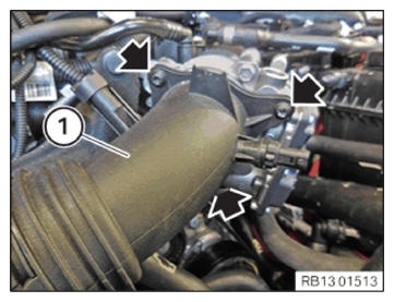
- Remove screws (arrows).
- Feed out charge air line (1) and place to one side.
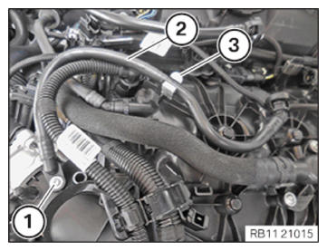
- Loosen screw (1).
- Guide tank ventilation line (2) out of clamp (3) and remove it.
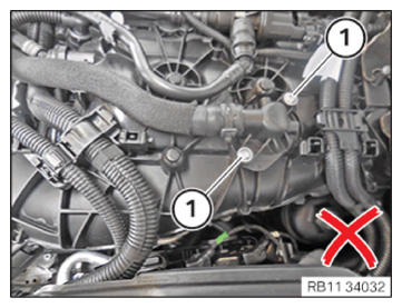
NOTE:
TECHNICAL INFORMATION
The tension rod screws and mounting bolts from the connecting neck on the intake plenum are not allowed to be opened.
The tension rod screws and mounting bolts from the connecting neck on the intake plenum are not allowed to be opened.
- Do not
release screws (1).
- Release the clamping collar (1) with the special tool 0 495 794 (17 2 050).
- Guide out the coolant hose (2) and remove it.
- Catch and dispose of escaping coolant.
- Unlock the locks (arrows).
- Feed out the wiring harness section (3) for the sensor system 2 and set it aside.
- Unlock lock (1).
- Thread out holder (2) and set aside.
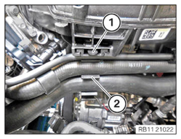
- Unlock plug connection (1) and disconnect.
- Loosen screw (2).
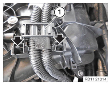
- Unlock the locks (arrows).
- Feed out the wiring harness section (1) for the injectors and ignition coils and put to one side.
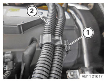
- Loosen clamp (1).
- Feed out the wiring harness section (2) for the injectors and ignition coils and put to one side.
- Guide tank ventilation line (1) out of clamp (2) and place it aside.
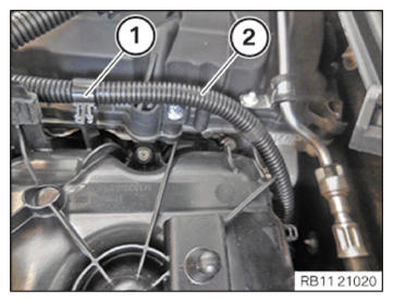
- Loosen clamp (1).
- Feed out the wiring harness section (2) for the sensor system 1 and set it aside.
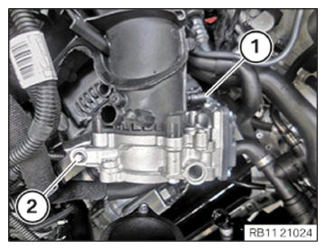
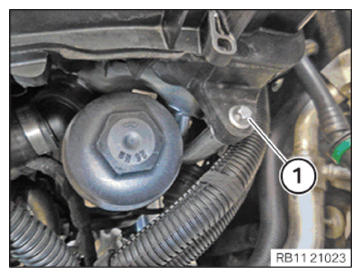
- Loosen screw (1).
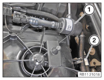
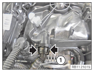
- Unlock plug connection (1) and disconnect.
- Unlock the locks (arrows).
- Feed the tank ventilation line (1) out and set it aside.
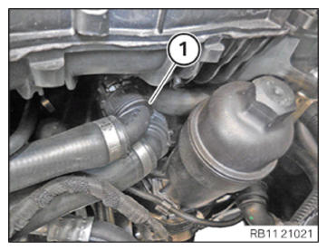
- Unlock and release the coolant feed line (1).
- Catch and dispose of escaping coolant.
NOTE:
TECHNICAL INFORMATION
Additional coolant can leakage. Make sure that no coolant enters the intake port of the cylinder head.
Additional coolant can leakage. Make sure that no coolant enters the intake port of the cylinder head.
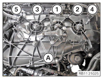
- Loosen screws in the order (5) to (1).
- Guide out the intake plenum (A) and remove it.
- Empty the remaining coolant (2) from the intake plenum (1).

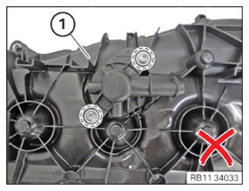
NOTE:
TECHNICAL INFORMATION
The tension rod screws and mounting bolts from the connecting neck on the intake plenum are not allowed to be opened.
The tension rod screws and mounting bolts from the connecting neck on the intake plenum are not allowed to be opened.
- Do not release screws in the marked area on the intake plenum (1).
NOTE:
TECHNICAL INFORMATION
The tension rod screws and mounting bolts from the connecting neck on the intake plenum are not allowed to be opened.
The tension rod screws and mounting bolts from the connecting neck on the intake plenum are not allowed to be opened.
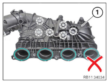
- Do not release screws in the marked area on the intake plenum (1).