Fill the high-temperature cooling system with the vacuum filling equipment
Further information is available.
Vacuum filling equipment
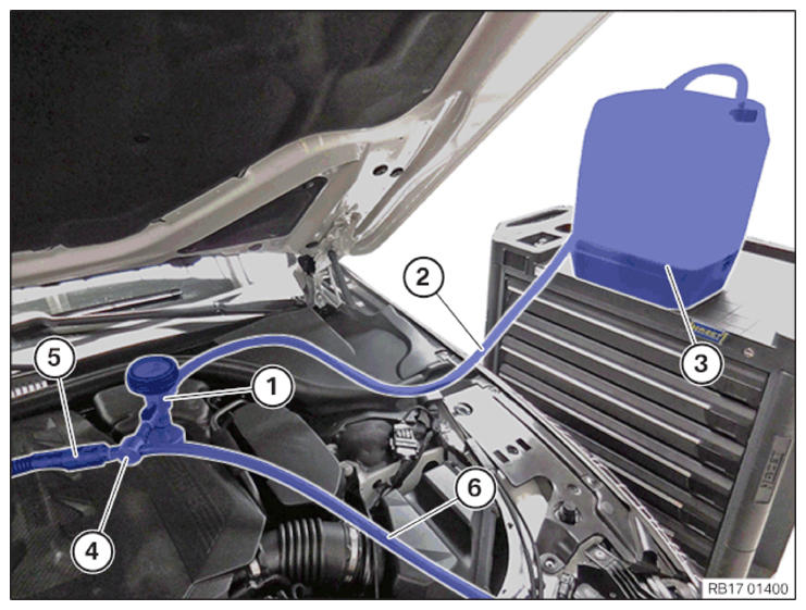
Vacuum filling equipment - connected to the coolant expansion tank
- Vacuum filling equipment with pressure gauge and shutoff valves
- Filling hose
- Fluid tank with coolant
- Venturi nozzle
- Compressed air connection (maximum of 6 bar)
- Out-going hose (lead out-going hose into a collecting vessel)
Prerequisite
The coolant expansion tank for the cooling system must be empty. The fluid tank of the vacuum filling equipment must have a sufficient quantity of premixed coolant, 1 I to 2 I more than the specified capacity for the vehicle. The fluid tank of the vacuum filling equipment must be positioned at the same height as the coolant expansion tank. The compressed air connection must have a pressure of 6 bar. Heating must be set to the maximum temperature.
Follow notes for repair work on the cooling system.
For additional information see:
17 00... INSTRUCTIONS FOR REPAIR WORK ON COOLING SYSTEM
Immobilization period-long fill of coolant!
Do not reuse used coolant.
When replacing and removing components which rely on the corrosion protection effect of the coolant, it is essential to change the coolant. The cooling system must therefore be emptied and refilled.
In the case of other removal work involving the draining of part quantities of coolant, the coolant level must be topped up with new coolant.
Filling without the vacuum filling equipment (watering can filling) is not permitted.
If this is not observed, there is a risk of component damage or engine damage.
The filling specification must be observed.
It is essential to visually check the vacuum filling equipment before use to check that it is functioning correctly and clean.
It is not permissible to operate the vehicle if the filling procedure has not been fully completed. Otherwise there may be functional limitations (degradation) or overheating.
A bleeding procedure is required after a part has been exchanged in the cooling system and/or after refilling the cooling system.
- Not the type of coolant
Coolant in the collecting vessel of vacuum filler device
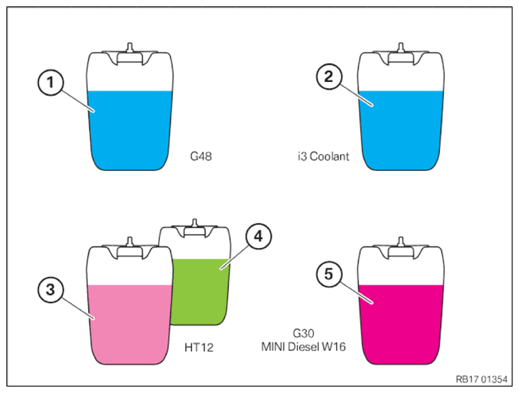
Choose the correct coolant for filling.
In general, a vehicle has to be filled with the coolant with which it is delivered from the factory.
- G48 (Blue) (BMW LC-87)
Must not be mixed with i3 Coolant or G30 MINI Diesel W16.
- i3 Coolant (Blue) (BMW LC-13)
Is used only for heater circuit i3. i3 Coolant must not be added to other coolant circuits or mixed with other coolants.
- HT12 (Pink) (BMW LC-18)
Must not be mixed with i3 Coolant or G30 MINI Diesel W16.
- HT12 (Green) (BMWLC-18)
Must not be mixed with i3 Coolant or G30 MINI Diesel W16.
- G30 (Pink) (BMW LC-07)
May be W16 used exclusively for the MINI Diesel. G30 must not be filled in the other coolant circuits or mixed with the other coolants.
Damage to the engine or components in high-voltage vehicles
Using the incorrect coolant may lead to corrosion or gel formation in the coolant circuit.
- Only use coolant that has been approved for the specific vehicle.
- Only fill the vehicle with the coolant with which it was delivered ex works.
- Only mix compatible coolants. The color does not allow any statement about coolant compatibility.
- Selection of the correct coolant exclusively via the part number.
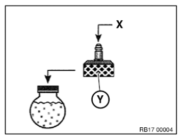
- Select a suitable adapter (Y) from the set of special tools 0494 417 (17 0100):
Type Engine Adapter (Y) from 170 100 G11/G12/G14/G15/G16 N63B4T3 170 113 - The fluid tank of the vacuum filling equipment must be filled with 1 I to 2 I more than the specified capacity of coolant for the vehicle.TECHNICAL DATA - HIGH-TEMPERATURE COOLANT CIRCUIT TILLING CAPACITY SPECIFICATION
High-temperature coolant circuit tilling capacity G30 N63B44T3 N63B44T3 8.75 I - Connect the selected adapter (Y) to the coolant expansion tank.
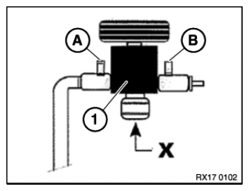
- Connect vacuum filling equipment to connection (X) of the adapter.
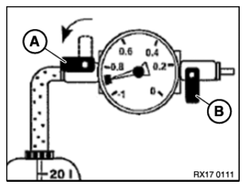
- Close shutoff valves (A) and (B) of the vacuum filling equipment (1).
(X) Expansion tank connection
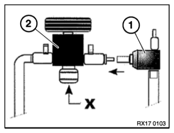
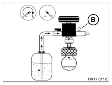
- Connect Venturi nozzle (1) to the vacuum filling equipment (2).
(X) Expansion tank connection
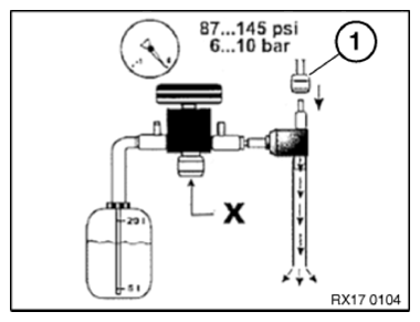
- Connect compressed air (1).
(X) Expansion tank connection
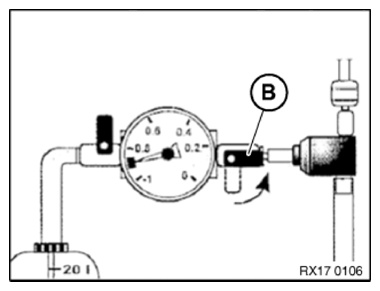
- Open shutoff valve (B).
The Venturi nozzle generates a flow noise.
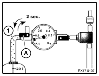
- Open shutoff valve (A) until the filling hose (1) is full without bubbles.
- Close the shutoff valve (A) again.
» The filling hose (1) has now been bled.
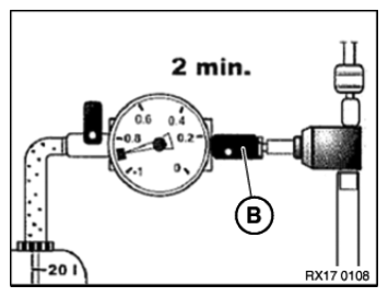
- Check the coolant hoses for porosity and replace porous coolant hoses as needed.NOTE: TECHNICAL INFORMATION
The coolant hoses contract during vacuum build-up. - After a vacuum of -0.7 to -0.95 bar has been reached in the coolant circuit (duration approximately 2 minutes), close the shutoff valve (B).
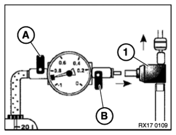
- Check whether shutoff valves (A) and (B) are closed.
- Disconnect the Venturi nozzle (1).
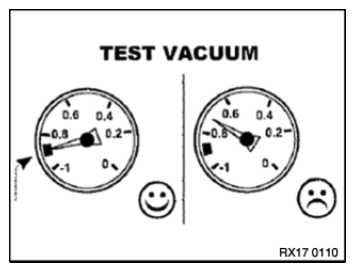
Check
- The vacuum in the coolant circuit must be maintained for at least 30 seconds.
Result
» Vacuum drops.
Measure
- Look for the leak, repair it and start the filling procedure from the beginning.
Check
- The vacuum in the coolant circuit must be maintained for at least 30 seconds.
Result
» Vacuum remains constant.
Measure
- Continue with filling.
- Keep shutoff valve (B) closed during the filling process.
- To fill the cooling system, open shutoff valve (A) to the fluid tank of the vacuum filling equipment.
- Stop the filling procedure when the needle in the pressure tester is on 0 bar or it no longer drops.
- If necessary, reduce remaining vacuum. To do so, open the shutoff valve (B).
- Remove the vacuum filling equipment with the adapter from the coolant expansion tank.
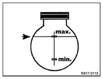
- Adjust the coolant level to the maximum mark.
- After filling the cooling system with the vacuum filling equipment, also perform the cooling system bleeding procedure.