Install the radiator of the high-temperature coolant circuit
Further information is available.
NOTE:
TECHNICAL INFORMATION
Notes on work at the cooling system form the basis of these repair instructions and must be complied with at all times.
For additional information see: 17 00... INSTRUCTIONS FOR REPAIR WORK ON COOLING SYSTEM
Notes on work at the cooling system form the basis of these repair instructions and must be complied with at all times.
For additional information see: 17 00... INSTRUCTIONS FOR REPAIR WORK ON COOLING SYSTEM
NOTE:
TECHNICAL INFORMATION
Make sure that the connections are locked correctly. The locks must engage audibly.
Make sure that the connections are locked correctly. The locks must engage audibly.
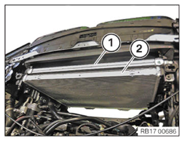
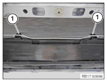
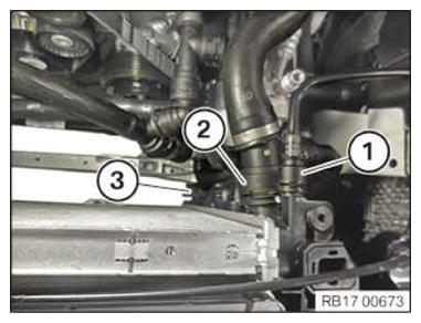
- Guide in radiator of low-temperature coolant circuit (1) with radiator of high-temperature coolant circuit (2) and install.
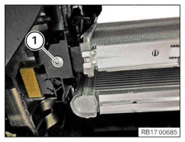
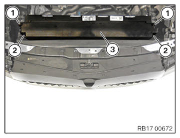
- Tighten screw (1) bottom cooling module, left.TIGHTENING TORQUES SPECIFICATION
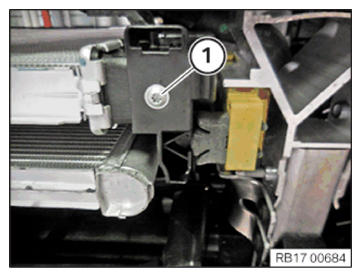
Radiator to cooling module, bottom TS6x20 Tightening torque 6 Nm - Tighten screw (1) bottom cooling module, right.TIGHTENING TORQUES SPECIFICATION
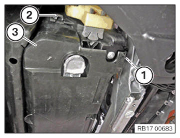
Radiator to cooling module, bottom TS6x20 Tightening torque 6 Nm - Insert and install the cover (3) at the bottom left cooling module.
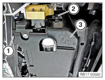
- Ensure that the lock (2) engages audibly.
- Ensure that the locking mechanism (1) engages audibly.
- Ensure that the locking mechanisms (1) engage audibly.
- Feed in and install cover (3) on cooling module, bottom right.
- Ensure that the lock (2) engages audibly.
- Ensure that the locking mechanism (1) engages audibly.
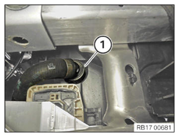
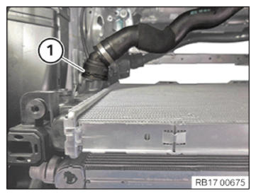
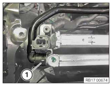
- Connect and lock coolant line (1).
- Make sure that the cooling line (1) engages audibly.
- Feed in air duct (2) in direction of arrow and install.
- Secure clamps (1).
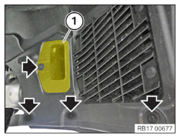
- Guide in and install cover (2), front right.
- Fasten the clamps.
- Tighten down screws (1).TIGHTENING TORQUES SPECIFICATION
Cover to front bumper screw Tightening torque 3 Nm - Thread in air duct (1) and install.
- Tighten the screws (arrows).TIGHTENING TORQUES SPECIFICATION
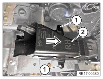
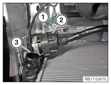
Cover to front bumper screw Tightening torque 3 Nm - Feed in and install the electric coolant pump (2).
- Secure the holder (1).
- Secure clamps (3).
- Connect and lock coolant line (1).
- Make sure that the coolant line (1) engages audibly.
- Connect and lock coolant line (1).
- Make sure that the coolant line (1) engages audibly.
- If fitted:
Connect and lock coolant line (3).
- Connect and lock coolant line (2).
- If fitted:
Connect and lock coolant line (1).
- Make sure that the coolant lines engage audibly.
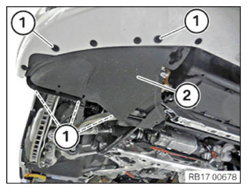
- Guide in and install cover (3) on cooling module at the top.
- Ensure that the locking mechanisms (2) engage audibly.
- Ensure that the locking mechanisms (1) engage audibly.
Follow-up work
- Refer to INSTALL FAN COWL .
- Refer to INSTALL THE REAR TOP CROSS CONNECTION .
- Refer to INSTALL FRONT CROSS CONNECTION .
- Refer to INSTALLING FRONT-END STRUT ON LEFT AND RIGHT .
- Refer to INSTALLING THE COVER ON THE LEFT AND RIGHT IN THE ENGINE COMPARTMENT AT THE TOP
- Refer to FILL THE HIGH-TEMPERATURE COOLING SYSTEM WITH THE VACUUM FILLING EQUIPMENT
- Refer to FILL THE LOW-TEMPERATURE COOLING SYSTEM WITH THE VACUUM FILLING EQUIPMENT
- Refer to VENT THE HIGH-TEMPERATURE COOLANT SYSTEM .
- Refer to VENTING THE LOW-TEMPERATURE COOLING SYSTEM .
- Refer to INSTALLING THE UNDERBODY PROTECTION OF THE STEERING GEAR OR THE FRONT THRUST FIELD .
- Refer to INSTALL THE FRONT UNDERBODY PROTECTION OR FRONT THRUST FIELD .