Install intake plenum
NOTE:
RISK OF DAMAGE
Improper routing of cables and wiring harnesses.
Trapped, crushed or damaged cables may cause short circuits and malfunctions.
Improper routing of cables and wiring harnesses.
Trapped, crushed or damaged cables may cause short circuits and malfunctions.
- Route all cables without abrasions, do not trap and crush.
NOTE:
TECHNICAL INFORMATION
Make sure that the connections are locked correctly. The locks must engage audibly.
Make sure that the connections are locked correctly. The locks must engage audibly.
NOTE:
TECHNICAL INFORMATION
Additional coolant can leakage. Make sure that no coolant enters the intake port of the cylinder head.
Additional coolant can leakage. Make sure that no coolant enters the intake port of the cylinder head.
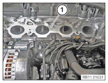
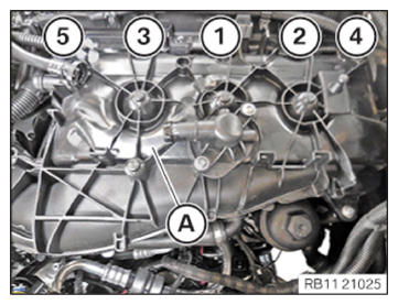
- Feed in and position the intake plenum (A) at the cylinder head.
- Tighten screws in the order (1) to (5).
NOTE: Tighten the bolts in 360 degree steps.TIGHTENING TORQUES SPECIFICATION
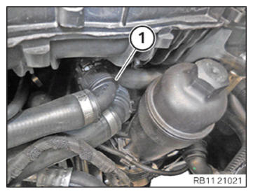
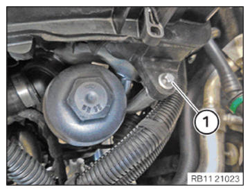
Intake plenum to cylinder head M6 Tightening torque 10 Nm - Connect and lock the coolant feed line (1).
- Make sure that the coolant feed line (1) engages audibly.
- Tighten down screw (1).TIGHTENING TORQUES SPECIFICATION
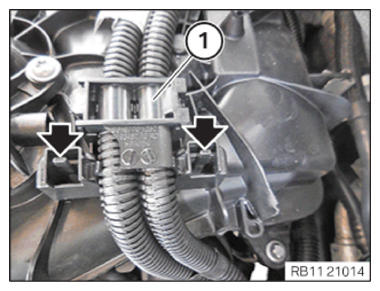
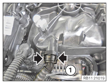
Intake plenum to support M6X25 Tightening torque 8 Nm - Guide in and Install the wiring harness section (1) for the injectors and ignition coils.
The locks (arrows) must engage audibly.
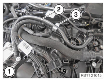
- Guide in and Install the wiring harness section (2) for the injectors and ignition coils.
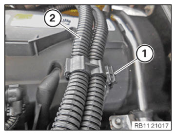
- Secure clamps (1).
- Guide in and install the wiring harness section (2) for sensor system 1.
- Secure clamps (1).
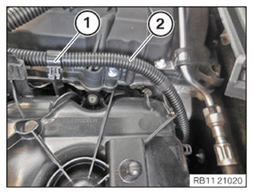
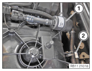
- Insert and install the tank vent line (1).
- Secure the tank vent line (1) to the clamp (2).
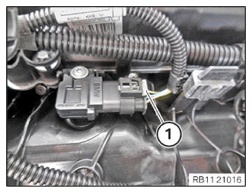
- Connect connectors (1) and lock.
- Make sure the connector (1) engages audibly.
- Tighten down screw (2).TIGHTENING TORQUES SPECIFICATION
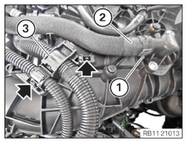
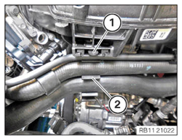
Throttle body to holder M6X25 Tightening torque 8 Nm - Insert and install the coolant hose (2).
- Fasten the clamping collar (1) with the special tool 0 495 794 (17 2 050).
- Feed in and install the wiring harness section (3) for sensor system 2.
- Make sure that you can hear the locks (arrows) engage.
- Insert and install the tank vent line (2).
- Secure the tank vent line (2) to the clamp (3).
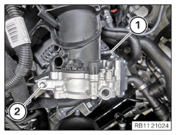
- Tighten down screw (1).TIGHTENING TORQUES SPECIFICATION
Tank vent line to intake plenum Oval-head screw Tightening torque 3 Nm - Connect connectors (1) and lock.
The connector (1) must engage audibly.
- Insert and install the tank vent line (1).
The locks (arrows) must engage audibly.
- Insert and install the holder (2).
- Ensure that the locking mechanism (1) engages audibly.
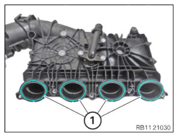
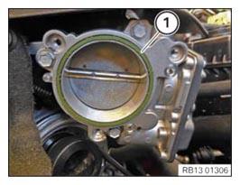
- Replace gasket (1).
Parts: Gasket
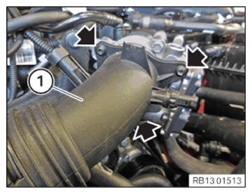
- Insert and install charge air line (1).
- Tighten screws (arrows).TIGHTENING TORQUES SPECIFICATION
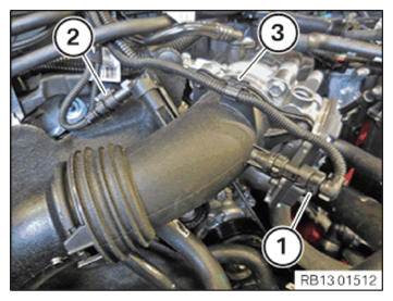
Charge air line to throttle body M6 tightening torque 8 Nm - Connect connectors (1) and lock.
- Connect connectors (2) and lock.
- Make sure you can hear the connectors (1) and (2) engage.
- Secure clamps (3).
Follow-up works
- Refer to INSTALLING THE TANK VENTING VALVE .
- Refer to INSTALLING CONTROL UNIT BRACKET .
- Refer to INSTALLING THE INTEGRATED POWER SUPPLY MODULE (PDM) .
- Refer to INSTALLING THE DME CONTROL UNIT .
- Refer to INSTALLING RESONATOR .
- Refer to CONNECTING NEGATIVE BATTERY CABLE .
- Refer to FILLING AND VENTING THE LOW-TEMPERATURE COOLANT CIRCUIT .
- Refer to INSTALLING ACOUSTIC COVER AT REAR .
- Refer to INSTALLING ACOUSTIC COVER .
- Refer to INSTALLING THE FRONT HOOD SEAL AT THE REAR .
- Refer to INSTALLING THE UNDERBODY PROTECTION OF THE STEERING GEAR OR THE FRONT THRUST FIELD .
- Refer to INSTALLING THE FRONT UNDERBODY PROTECTION OR FRONT THRUST FIELD .
- Refer to TAKING HOOD OUT OF THE SERVICE POSITION .