Check air intake system for tightness
Prerequisite
The intake filter housing or upper section of intake filter housing is removed.
NOTE:
TECHNICAL INFORMATION
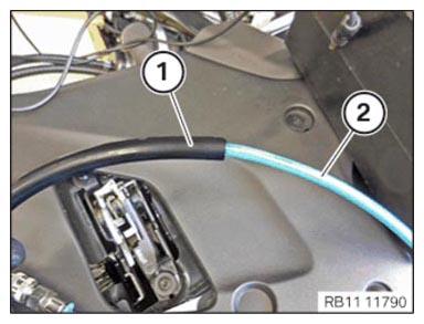
Excess pressure and vacuum lines can be recognized by the size of their fasteners and are color-coded blue and red respectively.
The overpressure line is marked blue.
The vacuum line is marked red.
Excess pressure and vacuum lines must not be mixed up. Mixing up the lines will result in engine damage.
NOTE:
Schematic diagram is for example purposes. Some parts may differ in certain details.
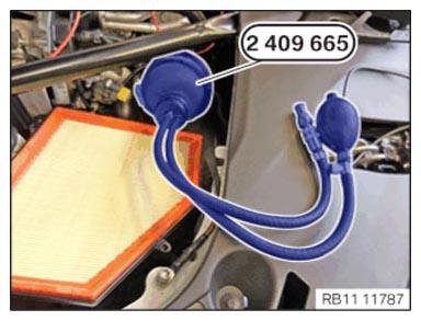
- Insert the special tool 2 409 665 into the clean air pipe and inflate.
- Seal the clean air pipe airtight using special tool 2 409665
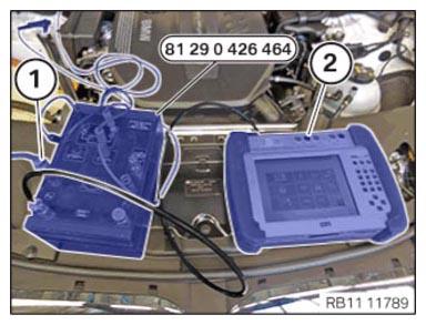
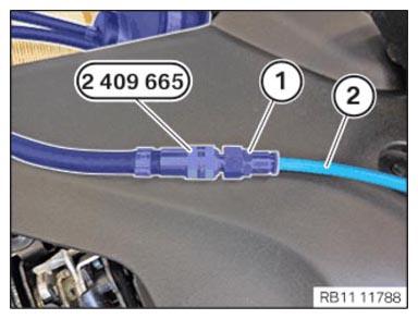
- Insert the blue overpressure line (2) of the special tool 0 426 464 into the quick-release coupling (1) of the special tool 2 409 665 up to the stop.
- Connect the blue overpressure line to the connector (1) with the special tool 0 426 464.
- Connect the Integrated Measurement Interface Box (1) with the help of a hose (e.g. hose with order number 81 31 2 357 800) with the special tool 0 426 464
The hose is fastened to the connector of the special tool 0 426 464.
- Follow diagnosis instruction.
- Disconnect the blue overpressure line (2) from the special tool 0 426 464.
The quick-release coupling stays attached.
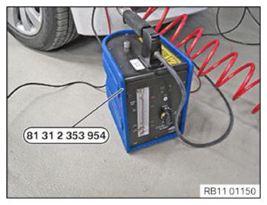
- Connect the pressure line (1) of the special tool
2 353 954 with the blue overpressure line (2)
.
- Put the special tool 2 353 954
into operation according to the operating instructions.
- Follow the instructions of the diagnostic system.
- Search for leakage smoke.
Leaks in the air intake system are detected through emerging smoke.