Installing the high-pressure rail at the cylinders 1 to 3
When assembling, it is essential to observe screwing sequences and tightening torques.
Failure to comply with the regulations can lead to leaks and damage.
Prepare the injectors for installation
Damage to the injector tips and Teflon ring.
Improper handling of the injector tips and Teflon ring can lead to malfunctioning of the injector.
- Avoid mechanical contact with injector tip.
- When exchanging Teflon ring, hands and work surface must be clean and free of oil. Do not use any lubricating agents.
- Do not use fingernails to slide Teflon ring on.
Before re-exchanging the injector, the Teflon ring must be replaceed. Once a Teflon ring has been installed, it may not be re-used. New injectors are supplied with a new Teflon ring.
After installation of a new Teflon ring on the injectors, the injector must be installed in the cylinder head within 10 minutes or protected with protective caps; otherwise, the Teflon ring will swell.
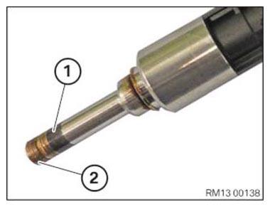
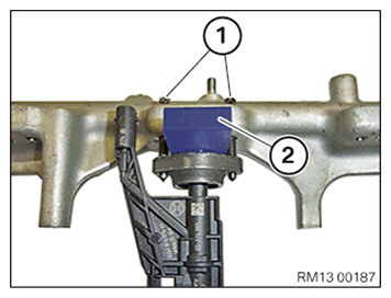
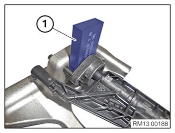
- Before installing the injectors: Replace the Teflon rings (1).
Parts: Teflon rings
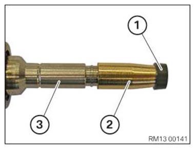
- Avoid mechanical contact with injector tip (2).
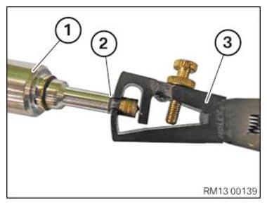
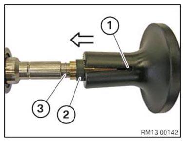
- Dismount the Teflon ring (2) with the special tool 0 495 757 (13 0 191) (3) from the set of special tools 0 495 756 (13 0 190) from the injector (1).
- If necessary, use a lint-free cloth to clean the cylindrical part of the injector tip. Do not use ultrasonic sound or other auxiliary materials.
- Do not clean injector tip.
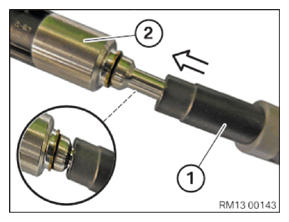
- Slide the new Teflon ring (1) onto the installation cone 0 496 771 (13 0 283) (2) from the set of special tools 0 496 668 (13 0 280) .
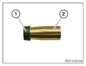
- Mount the Teflon ring (1) with the installation cone 0 496 771 (13 0 283) (2) from the set of special tools 0 496 668 (13 0 280) on the injector tip (3).
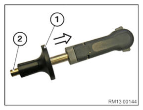
- Use the sliding sleeve (1) of the special tool 0 496 769 (13 0 281) from the set of special tools 0 496 668 (13 0 280) to push the Teflon ring (2) into the groove (3) on the injector.
- Adjust the expanded Teflon ring with the special tool 0 496 770 (13 0 282) (1) from the set of special tools 0 496 668 (13 0 280) to the installation dimension.
- Slide special tool 0 496 770 (13 0 282) (1) onto the injector (2) up to the stop.
- Push the sliding sleeve (1) of the special tool 0 496 770 (13 0 282) towards the rear and loosen the installation cone 0 496 771 (13 0 283) (2).
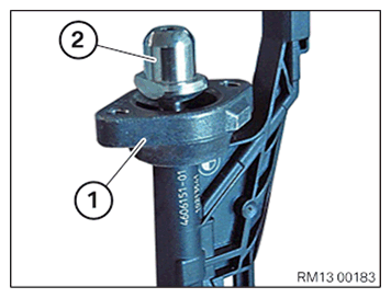
- Mount the holder (1) above the bayonet fitting (2) on the injector.
- If the holder (1) has a cast lug: Ensure that the installation position of the holder is correct.
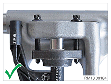
- If necessary, note the position of the cast lug:
The holder is mounted correctly when the cast lug lies in the rear.
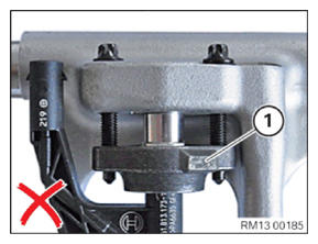
- If necessary, note the position of the cast lug:
The holder is mounted incorrectly when cast lug (1) lies in the front.
Damage to injectors.
Weld seams on the injector may tear due to incorrect distances between the rail and injector so that the injector must be replaceed.
- Insertion of the distance gauge is compulsory.
- Replace distance gauge, if a thickness of 8.5 mm is no longer given in the distance gauge.
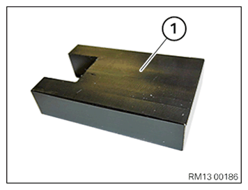
- Use the special tool (distance gauge) 2 358 022 (1).
- Replace (M5x30) screws.
Parts: Screws (M5x30)
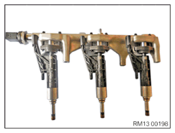
- Mount the injectors with the holders and the bolts (M5x30) (1) on the rail.
- Place the rail on a clean table so that the openings on the rail for the injectors point upwards.
The electrical injector connections must point towards the fuel pressure sensor.
- Slide the special tool (distance gauge) 2 358 022 (2) between the holders and the rail onto the injector head.
- Make sure that the special tool (distance gauge) 2 358 022 (2) rests flat on the retaining bridge.
- Hand-tighten both screws (M5x30) (1) uniformly until special tool (distance gauge) 2 358 022 (2) rests flat
against the rail and the holder.
- Remove special tool 2 358 022 (1).
- Repeat this operation for all injectors.
- Check injectors for loose fit at the rail.
- Align the position of the electrical injector connections parallel to the rail.
The injectors must be able to move freely.
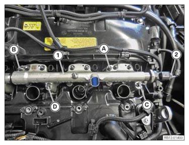
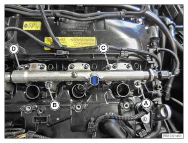
- Attach the rail (1) with the injectors to the cylinder head from the top.
- Ensure that the injector tips hit the holes provided in the cylinder head for this.
- Ensure that the guides on the injector are slid correctly into the guide bore holes in the cylinder head.
- Press down until a resistance can be felt, position screws (M6x70) (A), (B), (C) and (D), and turn them until hand-tight.
- Set torque wrench to 2 Nm.
- Tighten the screws (A,) (D), (B) and (C) in alternating order by 90° each with the torque wrench until the rail is positioned flush on the cylinder head.
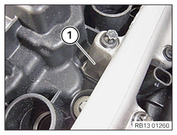
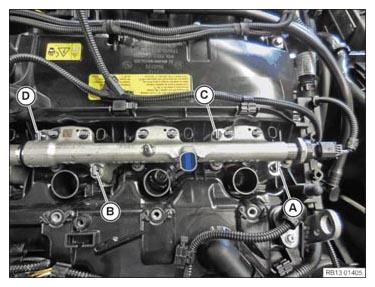
The illustration shows the rail lying flat on the cylinder head.
When assembling, it is essential to observe screwing sequences and tightening torques.
Failure to comply with the regulations can lead to leaks and damage.
- Tighten screw (A) by 5 Nm.
- Tighten screw (D) by 5 Nm.
- Tighten screw (B) by 5 Nm.
- Tighten screw (C) by 5 Nm.
- Connect and lock the connector (2).
The connector (2) must engage audibly.
- Make sure that the rail (1) rests flat against the cylinder head.
- Insert a wrench socket set into an extension.
Do not use a reversible ratchet or torque wrench.
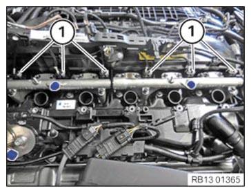
- Tighten the screws (M5x30) in pairs ((1) with (2), (3) with (4) with (5), (6)) alternately with 90° hand-tight.
- Set torque wrench to 5 Nm.
When assembling, it is essential to observe screwing sequences and tightening torques.
Failure to comply with the regulations can lead to leaks and damage.
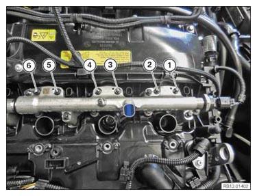
- Tighten the screws (M5x30) according to the following pattern:
- Fuel injector 1:
- Tighten screw (1) at an angle of rotation of 90°
±15° with the torque wrench.
- Tighten screw (2) at an angle of rotation of 90°
±15° with the torque wrench.
- Repeat the steps for screws (1) and (2) until 5 Nm is achieved for the two screws.
- Fuel injector 2:
- Tighten screw (3) at an angle of rotation of 90°
±15° with the torque wrench.
- Tighten screw (4) at an angle of rotation of 90°
±15° with the torque wrench.
- Repeat the steps for screws (3) and (4) until 5 Nm is achieved for the two screws.
- Fuel injector 3:
- Tighten screw (5) at an angle of rotation of 90°
±15° with the torque wrench.
- Tighten screw (6) at an angle of rotation of 90°
±15° with the torque wrench.
- Repeat the steps for screws (5) and (6) until 5 Nm is achieved for the two screws.
- Mark all bolts (1) to (6) with a vertical line (see figure).
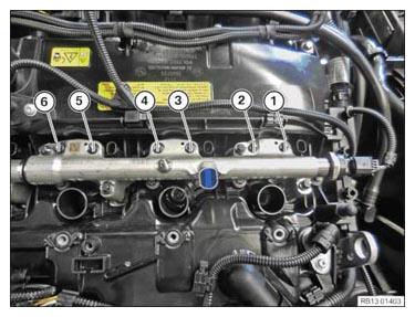
- Tighten screws using an angle of rotation.
- Tighten the screw (1) with an angle of rotation of 90° ±15°.
- Tighten the screw (2) with an angle of rotation of 90° ±15°.
- Tighten the screw (3) with an angle of rotation of 90° ±15°.
- Tighten the screw (4) with an angle of rotation of 90° ±15°.
- Tighten the screw (5) with an angle of rotation of 90° ±15°.
- Tighten the screw (6) with an angle of rotation of 90° ±15°.
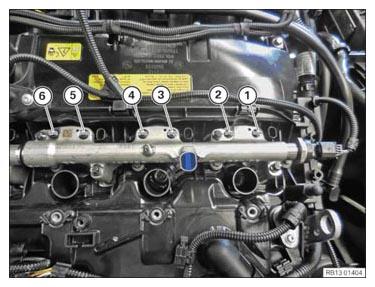
- Check if all screws (1) to (6) have been tightened with a 90° ±15° angle of rotation.
All markings (lines) must be horizontal (see Figure).
- Release the screws (M6x30) (A) to (D).
The screws must be released.
When assembling, it is essential to observe screwing sequences and tightening torques.
Failure to comply with the regulations can lead to leaks and damage.
- Tighten screw (A) at 5 Nm.
- Tighten screw (D) at 5 Nm.
- Tighten screw (B) at 5 Nm.
- Tighten screw (C) at 5 Nm.
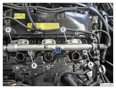
- Mark all the bolts (A) to (D) with a vertical line (see Figure).
- Tighten the screws (M6x30) (A) to (D) with a 90° angle of rotation.
- Check if all the screws (A) to (D) were tightened with an angle of rotation of 90°.
All markings (lines) must be horizontal (see Figure).
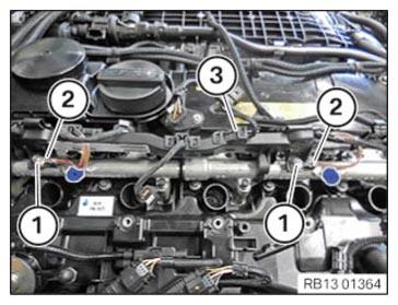
- Connect and lock all the connectors (1) to the injectors.
All connectors (1) must engage audibly.
- Thread the cable channel (3) in and install.
- Feed in ground cable (2) and install.
- Tighten the screws (1).
| Ground cable to rail | ||
|---|---|---|
| M6 | Tightening torque | 5 Nm |