Remove injectors
WARNING:
Working on 12 V electrical system.
Risk of short circuits! Risk of fire!
Risk of short circuits! Risk of fire!
- Make sure that there is no charger connected to the jump start terminal in the engine compartment.
- Detach battery ground lead from battery.
- For auxiliary batteries: Detach battery minus cables from all auxiliary batteries.
WARNING:
Working on fuel system.
Risk of fire! Danger of explosion!
Risk of fire! Danger of explosion!
- When working on the fuel system, make sure the workstation has sufficient ventilation, e.g., by means of extraction.
- Tightly seal off open lines and connections; collect any leakage fuel directly at the point of exit.
- No fire, sparks, open flames or smoking.
NOTE:
TECHNICAL INFORMATION
Collect and dispose of emerging fluids. Observe country-specific waste disposal regulations.
Collect and dispose of emerging fluids. Observe country-specific waste disposal regulations.
Preliminary work
- Refer to DISCONNECTING ALL BATTERY GROUND LEADS .
- Refer to REMOVING THE ACOUSTIC COVER .
- Refer to REMOVING INTAKE SILENCER HOUSING .
- Refer to REMOVE IGNITION COILS .
- Refer to REMOVING THE COVER ON LEFT AND RIGHT IN THE ENGINE COMPARTMENT AT THE TOP .
- Refer to REMOVE THE LEFT AND RIGHT FRONT-END STRUT
- Refer to REMOVE FRONT CROSS CONNECTION .
- Refer to REMOVE THE REAR TOP CROSS CONNECTION .
- Refer to REMOVING THE RIGHT UNFILTERED-AIR DUCT .
- Refer to REMOVING THE LEFT UNFILTERED-AIR DUCT .
- Refer to PARTIALLY RELEASING THE RIGHT CHARGE AIR LINE
- Refer to RELEASING THE LEFT CHARGE AIR LINE FROM THE EXHAUST TURBOCHARGER
- Refer to REMOVE RIGHT CLEAN AIR PIPE .
- Refer to REMOVE LEFT CLEAN AIR PIPE .
- Refer to REMOVING REAR UNDERBODY PROTECTION .
- Refer to REMOVING THE DME CONTROL UNIT FOR CYLINDERS 1 TO 4 .
- Refer to REMOVE THE INTEGRATED POWER SUPPLY MODULE (PDM) .
- Refer to REMOVING THE HOLDER FOR THE RIGHT-HAND DME CONTROL UNIT .
- Refer to PARTIALLY UNDOING WIRING HARNESS FROM RIGHT CYLINDER HEAD COVER .
- Refer to PARTLY LOOSENING THE WIRING HARNESS FROM THE CYLINDER HEAD COVER ON THE LEFT .
- Refer to REMOVING THE SOUND INSULATION ON THE RIGHT-HAND CYLINDER HEAD COVER .
- Refer to REMOVING THE SOUND INSULATION FROM CYLINDER HEAD COVER ON LEFT .
- Refer to REMOVE RIGHT RAIL .
- Refer to REMOVE THE HIGH-PRESSURE RAIL ON THE LEFT .
NOTE:
RISK OF DAMAGE
Damage to injectors.
Excessive force may damage the injector and this means having to replace the injector.
Damage to injectors.
Excessive force may damage the injector and this means having to replace the injector.
- Twist the injectors with a torsional movement of maximum 13 Nm.
NOTE:
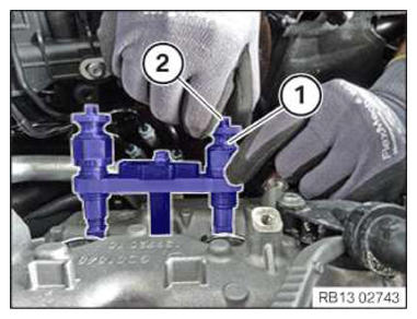
The description is for one component only. The procedure is identical for all further components.
NOTE:
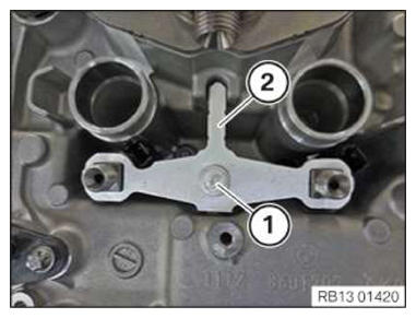
To provide a better overview: Shown with engine removed.
- Loosen screw (1).
- Remove hold-down device (2).
- Pull injectors upward out of cylinder head and remove.
If several injectors are removed, ensure that each injector is reinstalled in its original installation location (cylinder):
- Mark injectors.NOTE: TECHNICAL INFORMATION
To not exceed the maximum tensile force of 2000 N when pulling out the fixed injectors:
Use special tool 2 410 777! Using a correctly adjusted torque wrench and special tool 2 410 777 ensures that the maximum tensile force of 2000 N will not be exceeded at the injectors.
The injector must be replaceed if the torque wrench clicks when the injector is pulled out. - Unscrew the pull-out thread (1) from the special tool 0 496 885 (13 0 320)
.
- Screw in the pull-out thread (1) from special tool 0 496 885 (13 0 320) into special tool 2 410 777 .
- Lightly oil the pull-out thread (1) before using the special tool 2 410 777
and unscrew completely as shown.
The pull-out threads (1) are left-hand threads.
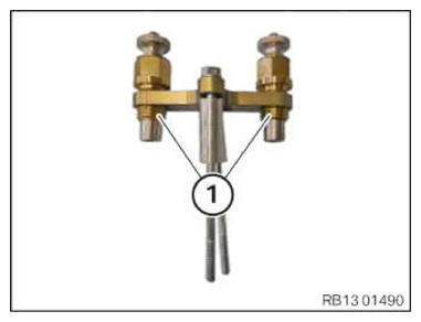
- Position the special tool 2 410 777 on the injector shaft.
- Screw in the screws (1) on the injector shaft for a few thread starts.
- Fully screw in the pull-out thread (2).
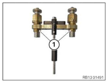
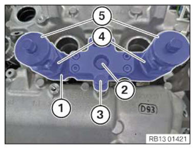
- Screw on the threaded sleeves (1) on to the injectors until the retaining pin (2) grips.
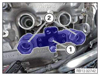
- Tighten the screws (2) and (3) of the special tool (1) 2 410 777
.TIGHTENING TORQUES SPECIFICATION
Special tool 2 410 777 to injector well M6 Tightening torque 8 Nm - Check whether the pull-out threads (4) are fully screwed in.
- Check whether the threaded sleeves (5) at the injectors are screwed on and retained.
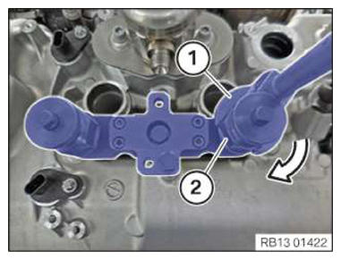
- Adjust the torque wrench to 13 Nm in a clockwise rotation.
- Position the torque wrench (1) and the special tool (2) 0 496 106 (11 8 720) on the hexagon head (3) of the special tool 2 410 777 .
- Turn the torque wrench (1) in the direction of arrow until the injector is extracted.
If the torque wrench clicks while pulling the injector out, then the injector must be replaced!
- Disassemble the special tool 2 410 777 and remove the injector.