Installing the exhaust turbocharger (cylinder head removed)
NOTE:
RISK OF DAMAGE
Damage of the electric wastegate valve controller.
Excessive force when removing and installing a jammed exhaust turbocharger may damage the electric wastegate valve controller.
Damage of the electric wastegate valve controller.
Excessive force when removing and installing a jammed exhaust turbocharger may damage the electric wastegate valve controller.
- Do not pull on the electric wastegate valve controller.
- Apply force only at the turbine housing and exhaust manifold.
- Do not pull on the compressor housing.
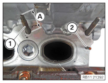
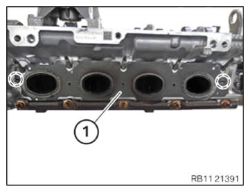
- Check the stud bolts (1) for damage and replace if necessary.
Parts: Stud bolts
- Check the screw-in depth (A) of the stud bolts (1); if necessary, continue screwing in.TECHNICAL DATA - SCREW-IN DEPTH OF UPPER STUD BOLTS SPECIFICATION
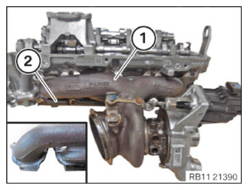
Screw-in depth of upper stud bolts on cylinder head Dimension A 30 mm - Check the stud bolt (2) for correct fit.NOTE: RISK OF DAMAGE
Damage to the surface.
The use of metal-cutting tools (e.g., emery cloths) for cleaning surfaces can damage them and lead to leaks and/or engine damage.- Do not use any metal-cutting tools.
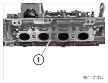
- Clean the sealing surfaces on the cylinder head (1) using special tool 0 495 102 (11 4 470). NOTE: RISK OF DAMAGE
Damage to the surface.
The use of metal-cutting tools (e.g., emery cloths) for cleaning surfaces can damage them and lead to leaks and/or engine damage.- Do not use any metal-cutting tools.
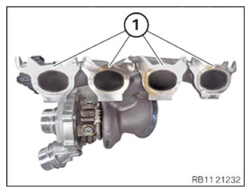
- Clean the sealing surfaces (1) on the exhaust turbocharger with the special tool 0 495 102 (11 4 470) .
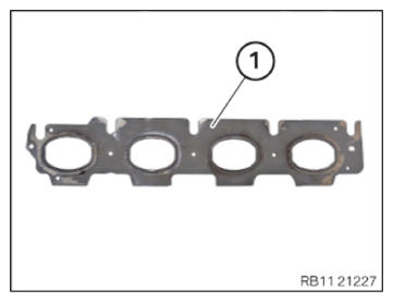
- Replace the seal (1).
Parts: Gasket
- Guide in and install the seal (1).
- Make sure that the seal (1) is correctly
installed in the guide pins in the marked
areas.CAUTION: Heavy component.
Heavy components can lead to injury or damage.- Remove and install heavy components with the aid of another person/other persons.
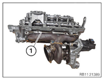
- Insert the exhaust turbocharger (1) downward into the trim strip (2) and align it flush on the cylinder head.NOTE: TECHNICAL INFORMATION
Note the installation position of the component. The component can be installed in various installation positions. - Mount the sliding bar (1).
The original BMW part number of the sliding bar (1) must be legible from the rear.
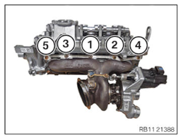
NOTE: TECHNICAL INFORMATION
When assembling, it is essential to observe screwing sequences and tightening torques.
Failure to comply with the regulations can lead to leaks and damage. - Replace nuts (1) to (5).
Parts: Nuts
- Tighten the nuts in the sequence (1) to (5).TIGHTENING TORQUES SPECIFICATION
Exhaust turbocharger to cylinder head M7
Observe tightening sequence!
Replace nuts.1. Joining torque 10 Nm 2. tightening torque 10 Nm 3. Joining torque 16 Nm 4. tightening torque 16 Nm 5. Tightening torque 16 Nm