Installing the exhaust turbocharger (cylinder head removed)
NOTE:
RISK OF DAMAGE
Damage of the electric wastegate valve controller.
Excessive force when removing and installing a jammed exhaust turbocharger may damage the electric wastegate valve controller.
Damage of the electric wastegate valve controller.
Excessive force when removing and installing a jammed exhaust turbocharger may damage the electric wastegate valve controller.
- Do not pull on the electric wastegate valve controller.
- Apply force only at the turbine housing and exhaust manifold.
- Do not pull on the compressor housing.
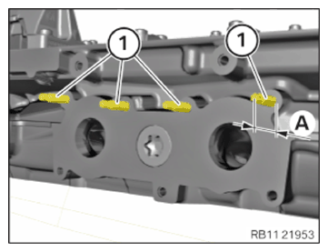
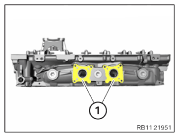
- Check screw-in depth (A) of upper stud bolts (1); if necessary, continue screwing in stud bolts or unscrew.
TECHNICAL DATA - SCREW-IN DEPTH OF UPPER STUD BOLTS SPECIFICATION
| Screw-in depth of upper stud bolts on cylinder head | |
| Dimension A | 30 mm |
NOTE:
RISK OF DAMAGE
Damage to the surface.
The use of metal-cutting tools (e.g., emery cloths) for cleaning surfaces can damage them and lead to leaks and/or engine damage.
Damage to the surface.
The use of metal-cutting tools (e.g., emery cloths) for cleaning surfaces can damage them and lead to leaks and/or engine damage.
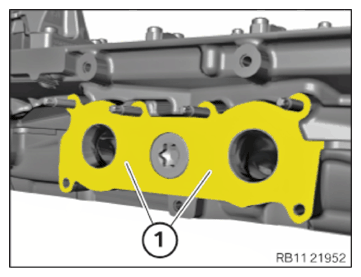
- Do not use any metal-cutting tools.
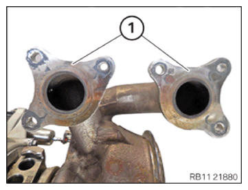
- Clean the sealing surfaces (1) on the cylinder head using special tool 0 495 102 (11 4 470)
.
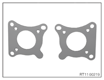
- Replace gaskets.
Parts : Seals
- Position the seals (1) on the cylinder head.
- Make sure the seals (1) are positioned correctly.
NOTE:
RISK OF DAMAGE
Damage to the surface.
The use of metal-cutting tools (e.g., emery cloths) for cleaning surfaces can damage them and lead to leaks and/or engine damage.
Damage to the surface.
The use of metal-cutting tools (e.g., emery cloths) for cleaning surfaces can damage them and lead to leaks and/or engine damage.
- Do not use any metal-cutting tools.
- Clean the sealing surfaces on the exhaust turbocharger (1) using special tool 0 495 102 (11 4 470)
.
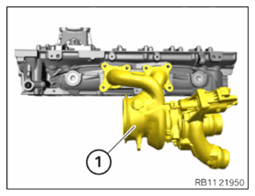
- Insert and install the exhaust turbocharger (1).
- Protect the exhaust turbocharger (1) from falling.
- Replace the nuts (1) and screws (2).
Parts : Nut and screws
- Insert the nuts (1) and screws (2).
NOTE:
Insert the screws in steps of 360 degrees.
- Tighten the nuts (1) and screws (2).

TIGHTENING TORQUES SPECIFICATION
| Exhaust turbocharger to cylinder head | ||
| M7 Replace screws. Replace nuts. |
1. Joining torque | 5 Nm |
| 2. tightening torque | 18 Nm | |
| 3. tightening torque | 18 Nm | |
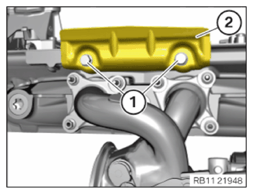
- Feed in and install the heat shield (2).
- Replace screws (1).
Parts : screw
- Tighten down screws (1).
TIGHTENING TORQUES SPECIFICATION
| Heat shield of exhaust turbocharger to cylinder head top | ||
| M8X12 Replace screws. |
Tightening torque | 19 Nm |