Install the complete full-flow oil filter
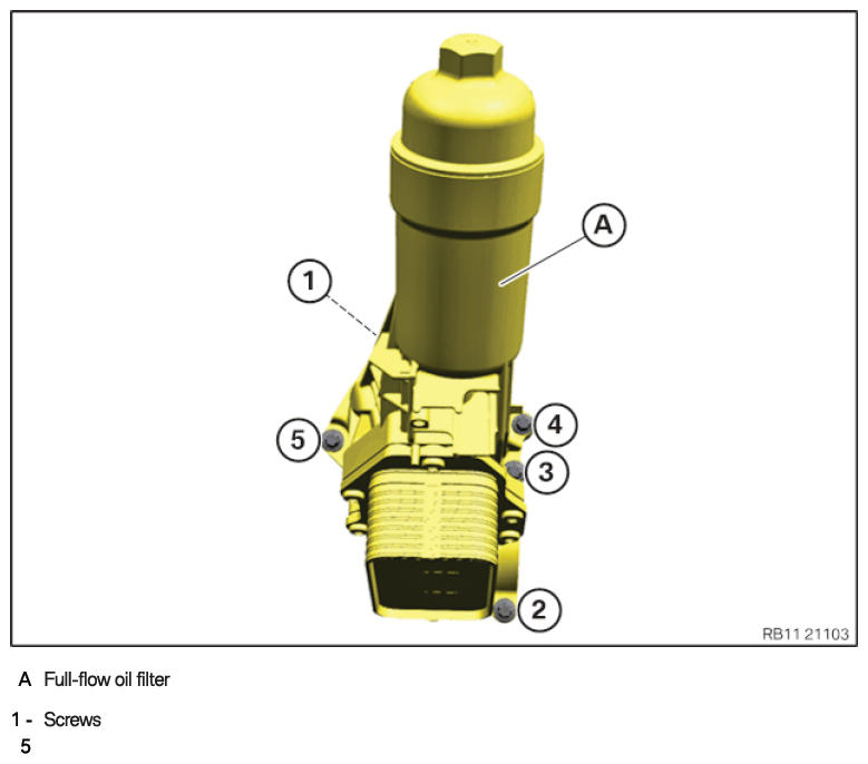
Full-flow oil filter
NOTE:
TECHNICAL INFORMATION
The sealing surfaces must be free of oil, grease and cleaning agents.
The sealing surfaces must be free of oil, grease and cleaning agents.
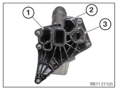
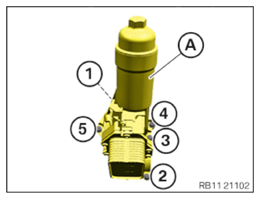
- Replace the gaskets (1), (2) and (3) on the full-flow oil filter.
Parts: Seals
NOTE: RISK OF DAMAGE
Damage to the surface.
The use of metal-cutting tools (e.g., emery cloths) for cleaning surfaces can damage them and lead to leaks and/or engine damage.- Do not use any metal-cutting tools.
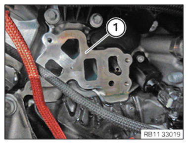
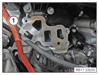
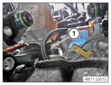
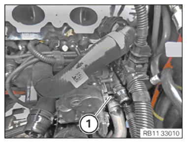
- Clean the sealing residue off the sealing surface (1) on the crankcase using the special tool 0 495 102 (11 4 470).
- Have a cleaning cloth ready.NOTE: RISK OF DAMAGE
Damage to the engine.
If the engine is manually rotated in the wrong direction of rotation, the engine can be damaged.- Only rotate the engine manually in the correct direction of rotation: a) clockwise when looking at the damper, or b) counterclockwise when looking at the chain drive, b) applies only if the timing chain is installed in the rear.
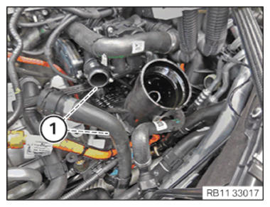
- Crank the engine with the special tool 0 493 380 (116 480) until the motor oil flows in the area of the oil duct (1).
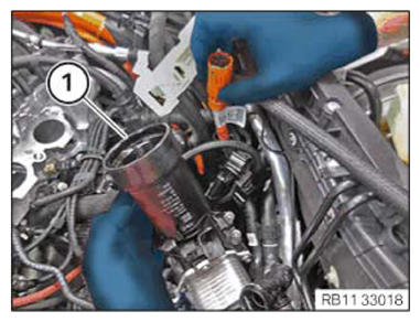
- Install full-flow oil filter (1) from the top and position it.
- Hand-tighten the screws (1).
- Hand-tighten the screws (1).
- Hand-tighten the screws (1).NOTE: TECHNICAL INFORMATION
When assembling, it is essential to observe screwing sequences and tightening torques.
Failure to comply with the regulations can lead to leaks and damage. - Tighten the screw at the full-flow oil filter (A) in the order (1) to (5).TIGHTENING TORQUES SPECIFICATION
Full-flow oil filter to crankcase M6
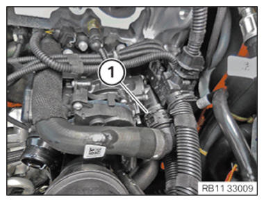
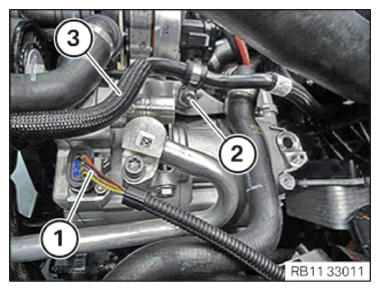
Observe tightening sequence.Joining torque 4 Nm Tightening torque 10 Nm - Connect and lock coolant line (1).
The coolant line (1) must audibly engage.
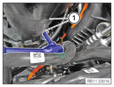
- Connect and lock coolant line (1).
The coolant line (1) must audibly engage.
- Connect and lock coolant line (1).
The coolant line (1) must audibly engage.
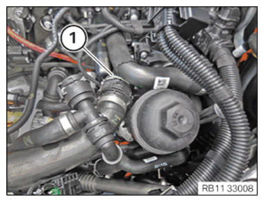
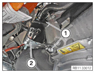
- Connect connectors (1) and lock.
The connector (1) must engage audibly.
- Feed in and position vacuum line (3).
- Tighten down screw (1).TIGHTENING TORQUES SPECIFICATION
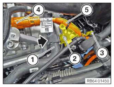
Vacuum hose holder to coolant pump Screw tightening torque 8.0 Nm - Replace screws (2) and (3).
Parts: screws.
- Position high-voltage cable (5) and connect and lock the connector (4).
- Tighten down screw (3).TIGHTENING TORQUES SPECIFICATION
Holder for oil filter housing Torx screw M6x16 Replace screw. tightening torque 4.0 Nm - Tighten down screw (2).TIGHTENING TORQUES SPECIFICATION
Holder for air conditioning compressor Hexagon screw M6x16
Replace screw.tightening torque 8 Nm - Insert coolant hose (1) in the bracket (arrow) and close the bracket.
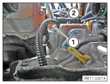
- Feed in and install the manifold bracket (2).
- Tighten down screw (1).TIGHTENING TORQUES SPECIFICATION
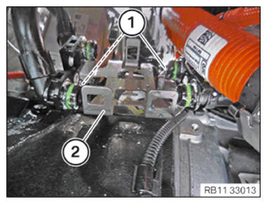
Manifold bracket to crankcase M6x16 Tightening torque 8 Nm - Feed in and position holder (2).
- Tighten the screws (1).TIGHTENING TORQUES SPECIFICATION
Thermostat holder to engine M6X16 Tightening torque 8 Nm - Feed in and position holder (2).
- Tighten down screw (1).TIGHTENING TORQUES SPECIFICATION
Holder of high-voltage cable to automatic transmission M6X12 Tightening torque 8 Nm
Follow-up work
- Refer to INSTALLING THE HOLDER FOR THE THERMOSTAT ON THE TRANSMISSION OIL LINES .
- Refer to INSTALLING THE THERMOSTAT ON THE TRANSMISSION OIL LINES .
- Refer to TIGHTENING THE OIL FILTER CAP .
- Refer to TOPPING UP THE MOTOR OIL .
- Refer to INSTALLING INTAKE PLENUM .
- Refer to INSTALLING THE TANK VENT VALVE .
- Refer to INSTALLING CONTROL UNIT BRACKET .
- Refer to INSTALLING THE INTEGRATED POWER SUPPLY MODULE (PDM) .
- Refer to INSTALLING THE DME CONTROL UNIT .
- Refer to INSTALLING THE ACOUSTIC COVER FOR THE ENGINE AT THE FRONT .
- Refer to INSTALLING CHARGE AIR LINE .
- Refer to INSTALLING RESONATOR .
- Refer to CONNECTING NEGATIVE BATTERY CABLE .
- Refer to FILLING AND VENTING THE HIGH-TEMPERATURE COOLANT CIRCUIT .
- Refer to FILLING AND VENTING THE LOW-TEMPERATURE COOLANT CIRCUIT .
- Refer to CHECKING/TOPPING UP THE OIL LEVEL IN THE AUTOMATIC TRANSMISSION .
- Refer to CHECKING ENGINE OIL LEVEL .
- Refer to INSTALLING ACOUSTIC COVER AT REAR .
- Refer to INSTALLING ACOUSTIC COVER .
- Refer to INSTALLING THE FRONT HOOD SEAL AT THE REAR .
- Refer to INSTALLING THE REAR THRUST FIELD .
- Refer to INSTALLING REAR UNDERBODY PROTECTION .
- Refer to INSTALLING THE UNDERBODY PROTECTION OF THE STEERING GEAR OR THE FRONT THRUST FIELD .
- Refer to INSTALLING THE FRONT UNDERBODY PROTECTION OR FRONT THRUST FIELD .
- Refer to TAKING HOOD OUT OF THE SERVICE POSITION .