Adjusting the valve timing of cylinder bank 1
Preliminary work
- Refer to CHECKING CAMSHAFT TIMING
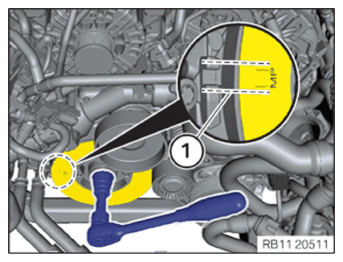
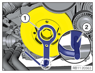
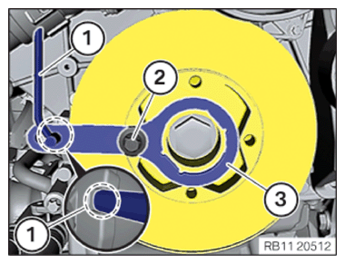
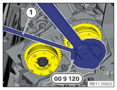
- Turn the engine clockwise on the central bolt until the installation position (MP) (1) of the vibration absorber aligns with the marks of the engine block.
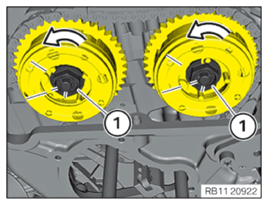
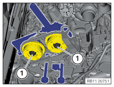
- Check the camshaft positions of bank 1.
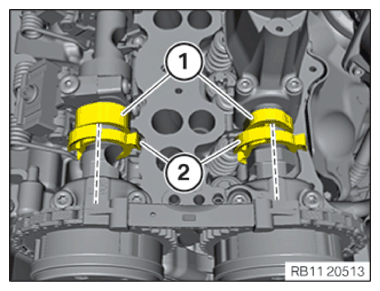
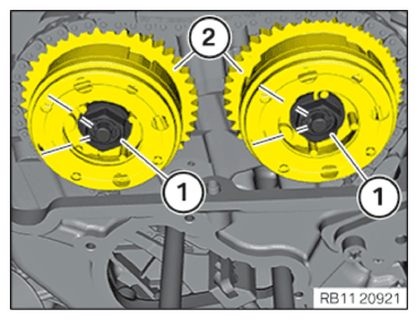
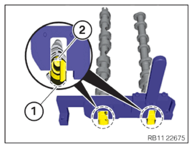
The cams (1) must be in the position shown.
The increment wheels (2) must form a line to the exhaust camshaft bearing cap and to the intake camshaft bearing cap.

- Make sure that the ground surfaces (2) of the camshafts point up.
- Make sure that the rounded surfaces (1) point downwards to the cylinder head.
- Check and evaluate the timing once again.
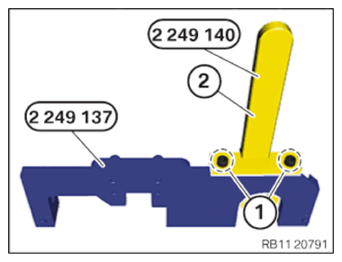
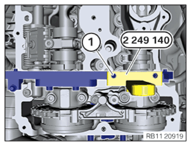
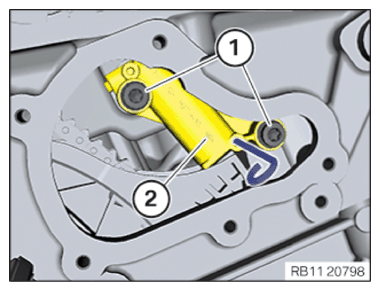
- Release screws (1) on the special tool 2 249 137 from the set of special tools 2 249 117.
- Remove the special tool 2 249 140 (2).
- Make sure that the VANOS central valves may only be secured with the special tools from the set of special tools 2 249 117.
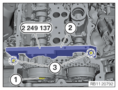
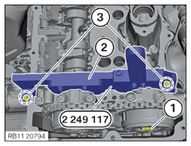
- Rotate the engine on the central bolt until the special tool 2 249 137 (2) can be positioned on the intake camshaft.
- Tighten special tool 2 249 137 (2) with screws (3) of the cylinder head covers.
| SWZ2249117 | ||
|---|---|---|
| Screw M6 | Tightening torque | 10 Nm |
- Slacken the VANOS central valve (1).
Do not completely unscrew the VANOS central valve (1).
Manually bring the VANOS central valve (1) onto the contact surface.
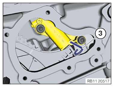
- Rotate the engine on the central bolt until the special tool (1) 2 249 140 can be positioned on the exhaust camshaft.
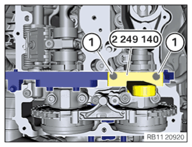
- Tighten the screws (1) on the special tool 2 249 140 from the set of special tools 2 249 117 .
| SWZ2249117 | ||
|---|---|---|
| Screw M6 | Tightening torque | 10 Nm |
- Make sure that the VANOS central valves may only be secured with the special tools from the set of special tools 2 249 117.
The special tool 2 249 117 (2) must be secured with screws (3) of the cylinder head cover.
- Slacken the VANOS central valve (1).
Do not completely unscrew the VANOS central valve
(1).
- Manually bring the VANOS central valve (1) onto the contact surface.
- Make straight marks on the VANOS central valves (1) and the VANOS adjusters (2) in the area of the hexagon head.
The angle must be 60°.
- Release the VANOS central valves (1) in the area of the hexagon head in an anti-clockwise direction until the upper mark of the VANOS central valve matches with the lower mark.
The rotational angle is 60°.
- Turn the engine counter-clockwise by 90° at central bolt.
Make sure that the special tools (1) 0 493 882 (11 9 190) and 0 496 366 (11 8 570) (2) do not collide with other components.
- Remove the special tool 0 496 366 (11 8 570) (2).
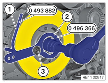
- Position the special tool (1) 0 493 882 (11 9 190) in the recess on the engine block.
- Turn the engine on the central bolt clockwise until the special tool 0 493 882 (11 9 190) (1) lies against special tool 0 496 366 (11 8 570) (2).
- Tighten special tool 0 496 366 (11 8 570 ) (2) hand-tight to the vibration absorber with a screw of the belt pulley (3).
- Remove special tool (1) 0 493 882 (11 9 190) .
Damage to timing chain or timing chain drive.
Turning the engine without chain tensioner or special tool can result in damage to the timing chain and timing chain drive.
- Always turn the engine with the chain tensioner or the special tool.
- Check that the screws (1) have been hand-tightened.
- Check preload of timing chain on special tool 2 249 162 at hexagon screw (2) with special tool 0 496 778 (00 9 460) to 0.6 Nm.
| Preload timing chain | ||
|---|---|---|
| tightening torque | 0.6 Nm | |
- Tighten VANOS central valves (1).
| VANOS central valve initial torque | ||
|---|---|---|
| VANOS central valve | Joining torque | 5 Nm |
- Turn engine on the central bolt until the special tool is aligned with the struts on the engine block.
- Attach the special tool 0 496 366 (11 8 570) (3) with a screw (2) of the belt pulley on the vibration absorber.
- Slide the crankshaft in the installation position with the special tool 0 493 882 (11 9 190) (1) on the bars and fix it.
- Tighten VANOS central valves (1).
| VANOS central valve second tightening | ||
|---|---|---|
| VANOS central valve | Joining torque | 30 Nm |
| Tightening torque | 50 Nm | |
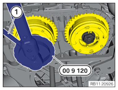
- Position the special tool 0 490 504 (00 9 120) (1) on the VANOS central valve of the intake side.
The magnetic foot of the special tool 0 490 504 (00 9 120 ) must be attached to a magnetic component in the engine compartment.
The flexible element of the special tool 0 490 504 (00 9 120) (1) may not collide with other components.

- Set the display of angle of rotation on the special tool 0 490 504 (00 9 120 ) to zero (arrow).
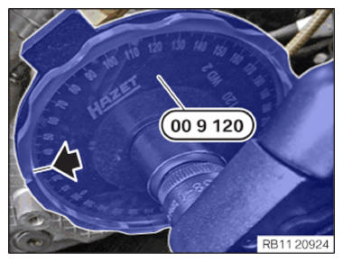
- Tighten the VANOS central valve of the intake side until the needle on the special tool 0 490 504 (00 9 120) is at 30° (arrow).
| VANOS central valve third tightening | ||
|---|---|---|
| VANOS central valve | Angle of rotation | 30° |
- Position the special tool 0 490 504 (00 9 120 ) (1) on to the VANOS central valve of the exhaust side.
The magnetic foot of the special tool 0 490 504 (00 9 120) must be attached to a magnetic component in the engine compartment.
The flexible element of the special tool 0 490 504 (00 9 120) (1) may not collide with other components.
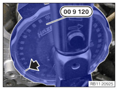
- Set the display of angle of rotation on the special tool 0 490 504 (00 9 120 ) to zero (arrow).
- Tighten the VANOS central valve on the exhaust side until the needle on special tool 0 490 504 (00 9 120 ) is at 30° (arrow).
| VANOS central valve third tightening | ||
|---|---|---|
| VANOS central valve | Angle of rotation | 30° |
- Loosen screws (2).
- Remove the special tool 2 249 117 (1).


- Remove special tool 0 493 882 (11 9 190) (1).
- Release the screw (2) of the belt pulley.
- Remove special tool 0 496 366 (11 8 570) (3).

- Check the camshaft positions of bank 1.
Cams (1) must be in the position shown.
The increment wheels (2) must form a line to the exhaust camshaft bearing cap and to the intake camshaft bearing cap.
- Make sure that the ground surfaces (2) of the camshafts point up.
- Make sure that the rounded surfaces (1) point downwards to the cylinder head.
- Check and evaluate the timing once again.
- Crank the engine on the central bolt twice in a clockwise direction until the installation position (MP) (1) of the vibration absorber aligns with the marks of the engine block.
- Position special tool 0 496 366 (11 8 570) (3) on the vibration absorber.
- Position the special tool 0 493 882 (11 9 190) (1) in the special tool 0 496 366 (11 8 570 ) (3).
The special tool 0 493 882 (11 9 190 ) (1) must not be inserted very far as the special tool 0 493 882 (11 9 190) (1) may collide with other components while turning the crankshaft.
- Rotate the engine on the central bolt in direction of engine rotation until the special tool aligns with the engine block marks.
- Tighten special tool 0 496 366 (11 8 570 ) (3) hand-tight to the vibration absorber with a screw of the belt pulley (2).
- Slide the crankshaft in the installation position with the special tool 0 493 882 (11 9 190 ) (1) at the marks and fix it.
Check
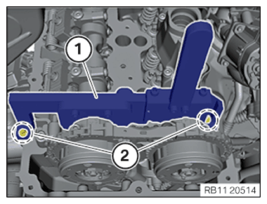
- Position special tool 2 249 117 (1) on the camshafts of cylinder bank 1.
- Check whether the camshafts can be fixed with the special tool 2 249 117 (1).
- Check whether the special tool 2 249 117 (1) can be brought onto the contact surface for the cylinder head with 2 screws (2) of the cylinder head cover.
Result
» The camshafts can be fastened. Measure
- Valve timings are OK.
Loosen screws (2).
Remove the special tool 2 249 117 (1). Continue the repair in the next step.
Result
» The camshafts cannot be fastened. Measure
- Adjust the timings of cylinder bank 1.
- Remove special tool 0 493 882 (11 9 190 ) (1).
- Release the screw (2) of the belt pulley.
- Remove special tool 0 496 366 (11 8 570) (3).
Installing the special tool to secure the camshafts of cylinder bank 1
If the check finds that the valve timings are incorrect, they must be adjusted.
For additional information, see: NOTES ON CHECKING AND ADJUSTING THE TIMING .
Check
- Position special tool 2 249 117 (1) on the camshafts of cylinder bank 1.
- Check if the camshafts can be fastened with the special tool 2 249 117 (1).
- Check if the special tool 2 249 117 can be brought in contact with the cylinder head using the two screws of the cylinder head cover (2).
Result
» The camshafts can be fastened.
Measure
- Timings are OK.
Loosen screws (2).
Remove the special tool 2 249 117 (1). Continue the repair in the next step.
Result
» The camshafts cannot be fastened. Measure
- Adjust the timings of cylinder bank 1.
Removing the special tool to pretension the timing chain at cylinder bank 1
Damage to timing chain or timing chain drive. Turning the engine without chain tensioner or special tool can result in damage to the timing chain and timing chain drive.
- Always turn the engine with the chain tensioner or the special tool.
- Release timing chain on the special tool 2 249 162 by turning the hexagon screw (2).
- Release the special tool 2 249 162 in the areas (1) and remove it.
Installing the hydraulic chain tensioner of cylinder bank 1
Damage to timing chain or timing chain drive.
Turning the engine without chain tensioner or special tool can result in damage to the timing chain and timing chain drive.
- Always turn the engine with the chain tensioner or the special tool.
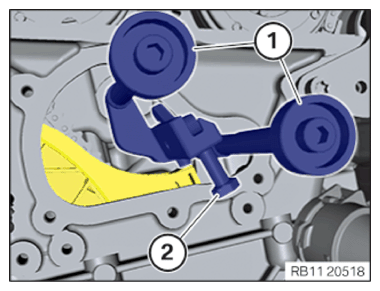
- Feed in and position the hydraulic chain tensioner (2).
- Tighten the screws (1).
| Chain tensioner to cylinder head | ||
|---|---|---|
| screw | Tightening torque | 13 Nm |
- Remove the special tool 0 491 012 (11 4 120) or transportation retainer (3) from the bore.
Removing special tool for fixing camshafts on bank 1
- Loosen screws (2).
- Remove the special tool 2 249 117 (1).
Remove the special tools to disconnect the crankshaft
- Remove special tool 0 493 882 (11 9 190) (1).
- Release the screw (2) of the belt pulley.
- Remove special tool 0 496 366 (11 8 570 ) (3).
Install the sealing cap on the cylinder head of cylinder bank 1
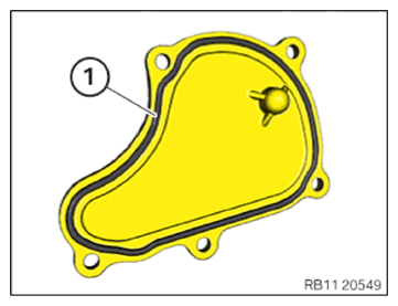
- Replace the seal (1).
Parts : Gasket
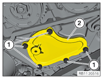
- Position the sealing cap (2) on the cylinder head.
- Tighten down screws (1).
| Sealing cap to cylinder head | ||
|---|---|---|
| M6x20 screw | Tightening torque | 9.5 Nm |