Installing the crankshaft (B48 technical update 0/1)
CAUTION:
Heavy component.
Heavy components can lead to injury or damage.
Heavy components can lead to injury or damage.
- Remove and install heavy components with the aid of another person/other persons.
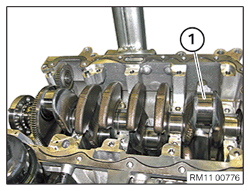
- Guide in and install crankshaft (1).NOTE: TECHNICAL INFORMATION
The crankshaft bearing cap, main bearing shell and guide bearing shell are aligned with each other.Always install the crankshaft bearing cap, main bearing shells and guide bearing shells in the cylinder from which they were removed.
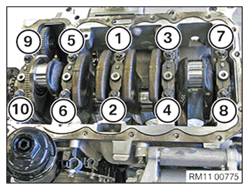
- Observe numbering on the main bearing cap.
- Position the main bearing cap.
- Tighten the screws in the following sequence: (1) - (10).TIGHTENING TORQUES SPECIFICATION
Main bearing cap to crankcase M10x1.5 Replace screws. 1. Jointing torque 25 Nm 2. Angle of rotation 60° 3. Angle of rotation 60° Checking the crankshaft side clearance
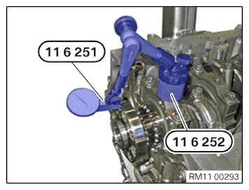
Check
- Attach the dial gauge 0493 144 (11 6 251)
with the tripod 0493 145 (11 6 252)
to the engine and measure the side clearance of the crankshaft.TECHNICAL DATA - AXIAL PLAY OF CRANKSHAFT SPECIFICATION
Axial play of crankshaft min. 0.060 mm max. 0.250 mm Result
» The side clearance has been exceeded.
Measure
- Replace worn components.
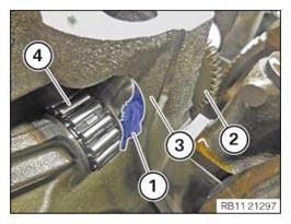
- Guide out a lint-free cleaning cloth (1) between the counterbalance shaft (2) on the intake side and crankcase (3) and remove it.
- Ensure that needle bearing (4) is not
damaged.
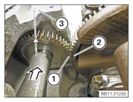
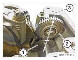
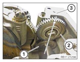
- Bring or adjust crankshaft (2) to the TDC position.
- Position counterbalance shaft (1) on the intake side in the direction of the arrow on crankshaft (2).
- The mark on gear (1) on the intake side of the counterbalance shaft must point upwards, perpendicular
to the sealing surface of oil sump (3).
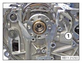
- Replace the screw (1).
Parts: Screw
- Screw, screw (1) into the counterbalance shafts on the intake side.
- Do not
tighten screw (1) since otherwise the counterbalance shafts can no longer be positioned in the next step.
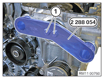
- Rotate the crankshaft to the TDC of the first cylinder.
- Mount the special tool 2288 054
and abut the bolts (1).NOTE: The description is for one component only. The procedure is identical for all further components.
- Make sure the special tool 2288 054 is correctly fitted in the guides (1) of the counterbalance shafts (2).
- If necessary, turn the crankshaft slightly.
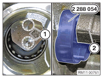
- Tighten special tool 2288 054. TIGHTENING TORQUES SPECIFICATION
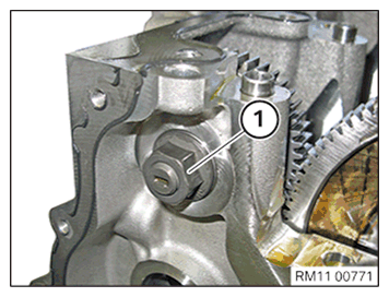
Special tool 2288 054 to crankshaft Tightening torque 20 Nm - Tighten screw (1) of the counterbalance shaft on the intake side.TIGHTENING TORQUES SPECIFICATION
Drive wheel to counterbalance shafts Screw
Replace screws.1. Tightening torque 20 Nm 2. Angle of rotation 180° - Loosen screws (1).
- Guide the special tool 2288 054
out and remove.
- Vehicles up to year of manufacture 07/16
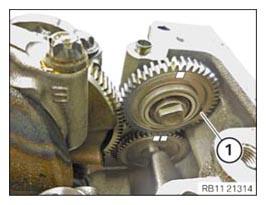
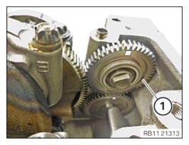
- Guide in and install intermediate wheel (1).
- Vehicles up to year of manufacture 07/16
- The marks on gear (1) and also on intermediate wheel (2) must point upwards, perpendicular to the oil sump sealing surface (3).
- Marking on intermediate wheel (2) of the counterbalance shaft at exhaust side: a square.
- Marking on the gear (1) of the counterbalance shaft, exhaust side: two squares.
- Vehicles from year of manufacture 07/16
- Guide in and install intermediate wheel (1).
- Vehicles from year of manufacture 07/16
- The marks on gear (1) and also on intermediate wheel (2) must point upwards, perpendicular to the sealing surface of oil sump (3).
- Marking on intermediate wheel (2) of the counterbalance shaft at exhaust side: a square.
- Marking on gear (1) on counterbalance shaft, exhaust side: a triangle.
- Move intermediate wheel (1) in the direction of the arrow to gear (2) of the crankshaft.
- Tighten nut (3).TIGHTENING TORQUES SPECIFICATION
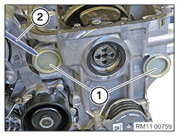
Idler gear to crankcase M12X1.5 1. Tightening torque 10 Nm 2. Angle of rotation 45° - Replace the sealing cap (1).
Parts: Sealing cap
- Make sure the O-rings of the sealing cap (1) are fitted correctly.
- Mount both sealing caps (1).