Disassemble cylinder head
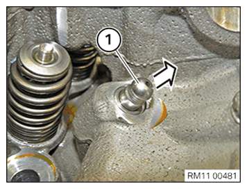
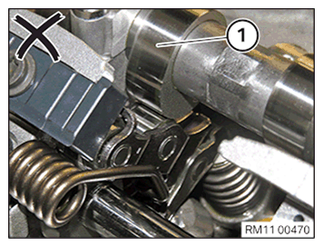
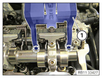
Checking the position of the intake camshaft (cylinder head removed)
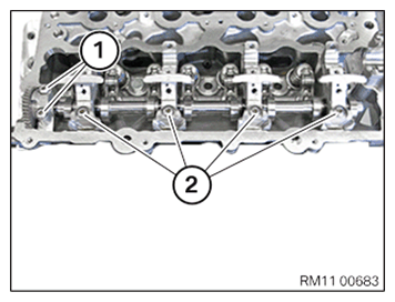
Check
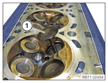
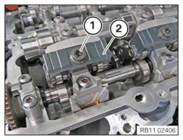
- Check position of the intake camshaft on the respective cylinders.
Result
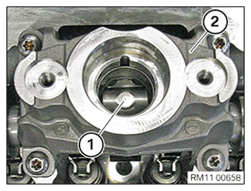
» Cam (1) of the intake camshaft runs on the intermediate lever.
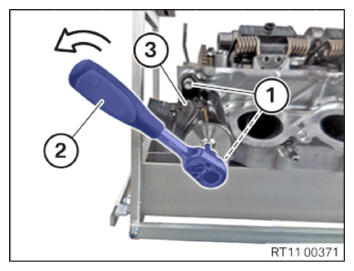
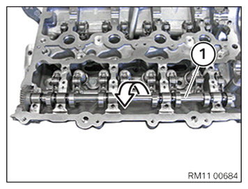
Measure
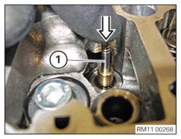
- Continue to crank the intake camshaft on the mounting flats.
Remove the torsion springs
Additional information is available.
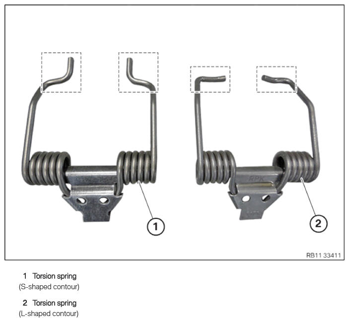
Torsion spring
CAUTION: Spring preload.
Danger of injury!- The use of the specified special tool (tool) is mandatory.
- The described operation must be carried out properly.
NOTE: TECHNICAL INFORMATION
Wear safety goggles.NOTE: TECHNICAL INFORMATION
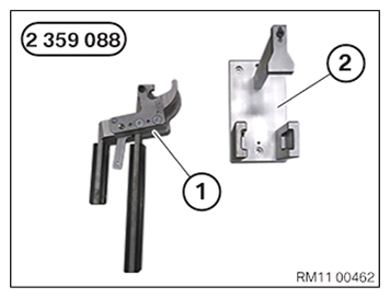
Special tool 2 359 088 is used to disassemble or install the torsion spring. Due to technical changes in the torsion spring, special tool 5 A0B 120 is mounted on existing special tool 2 359 088 .
Information on modification can be found in the further information.NOTE: TECHNICAL INFORMATION
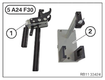
Alternative to the new special tool SWZ: 5 A24 F30 , the already known special tool SWZ: 2 359 088 can be used in modified form.
Information on modification can be found in the further information.
The modified special tool is downwards compatible.NOTE: TECHNICAL INFORMATION
When replacing one or more torsion springs:
When removing the torsion spring, it is imperative to note the part number of the torsion spring.
Mixed installation of the torsion springs is only permitted in combination with the appropriate intermediate lever.
For further information on possible combinations, see the applicable BMW parts catalogue. - Prepare set of special tools 2 359 088
for removing the torsion spring with an S-shaped contour:
Number Description 1 Clamping lever 2 Mount for clamping lever (for torsion spring with an S-shaped contour) - Prepare set of special tools 5 A24 F30
or alternatively modified special tool 2 359 088
for removing the torsion spring with an L/S-shaped contour:
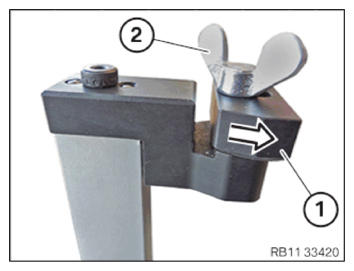
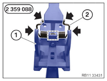
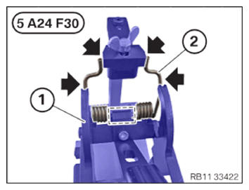
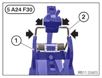
Number Description 1 Clamping lever 2 Mount for clamping lever (for torsion spring with an L/S-shaped contour) - Version with torsion spring with an S-shaped contour using special tool 5 A24 F30 or modified special tool 2 359 088:
Bring the shaped element (1) to the contact surface in the direction of arrow .
Hand-tighten the wing screw (2).
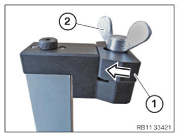
- Version with torsion spring with an L-shaped contour using special tool 5 A24 F30 or modified special tool 2 359 088:
Bring the shaped element (1) to the contact surface in the direction of arrow .
Hand-tighten the wing screw (2).
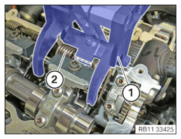
- Open the clamping lever (1) and position on the torsion spring (2).
- Ensure that the clamping lever (1) lies flat in the area (2) on the cylinder head.
- Close the clamping lever (1) carefully
until the retaining hook (3) engages audibly.
Check
- Check whether the clamping lever (1) is positioned correctly in the marked areas
on the torsion spring.
Result
» The clamping lever (1) is not positioned correctly on the torsion spring.
Measure
- Carefully release the clamping lever (1) and repeat the process.
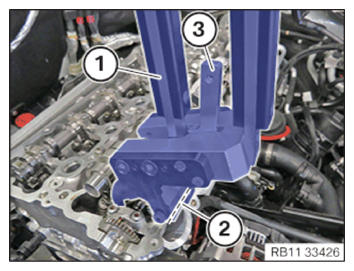
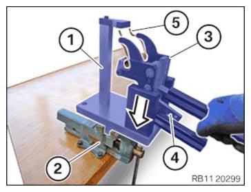
- Clamp the mount (1) in the vice (2).
- Position the clamping lever (3) with the preloaded torsion spring (5) in the mount (1) in the direction of arrow.
The retaining hook (4) of the clamping lever (3) is used for releasing the clamping lever (3).
The torsion spring (5) is thus released.
- Version with torsion spring with an S-shaped contour and the special tool 2 359 088
Carefully unlock the clamping lever (1) of the special tool 2 359 088 in the corresponding mount.
Make sure that the torsion spring (2) lies correctly in the lateral guides (arrows) and mark of the clamping lever (1) during releasing.
Place the torsion spring (2) neatly in the special tool 0 495 105 (11 4 480) .
- Version with torsion spring with an S-shaped contour and special tool 5 A24 F30 or modified special tool 2 359 088:
Carefully unlock the clamping lever (1) of special tool 5 A24 F30 or alternatively of modified special tool 2 359 088 in the corresponding mount.
Make sure that the torsion spring (2) lies correctly in the lateral guides (arrows) and mark of the clamping lever (1) during releasing.
Place the torsion spring (2) neatly in the special tool 0 495 105 (11 4 480) .
- Version with torsion spring with an L-shaped contour and special tool 5 A24 F30 or modified special tool 2 359 088:
Carefully unlock the clamping lever (1) of the special tool 5 A24 F30 or of the modified special tool 2 359 088 in the corresponding mount.
Make sure that the torsion spring (2) lies correctly in the lateral guides (arrows) and mark of the clamping lever (1) during releasing.
Place the torsion spring (2) neatly in the special tool 0 495 105 (11 4 480) .
- Repeat the operations for the remaining torsion springs.
Removing all gates
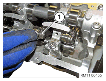
- Loosen screw (1).
- Remove the gate (2) and place it arranged in order into 0 495 105 (11 4 480) .
- Repeat the step for all the gates.
Removing all intermediate levers
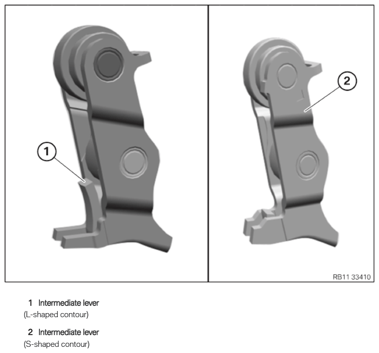
Intermediate lever
NOTE: TECHNICAL INFORMATION
When replacing one or more intermediate levers:
When removing the intermediate lever, it is imperative to note the part number of the intermediate lever.
Mixed installation of the intermediate levers is only permitted in combination with the appropriate torsion spring.
For further information on possible combinations, see the applicable BMW parts catalogue.NOTE: The description is for one component only. The procedure is identical for all further components. - Remove the intermediate lever (1) and arrange it in the special tool 0 495 105 (11 4 480)
in order.
Remove intake camshaft
- Make sure that the exhaust camshaft bearing cap is placed in the correct position in the special tool 0 495105 (11 4 480)
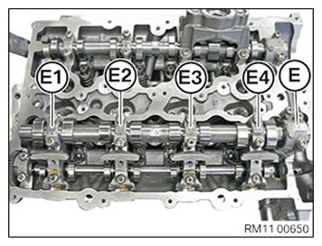
.NOTE: The intake camshaft bearing caps are legibly labelled from the intake side with E1, E2, E3, E4 and E.NOTE: Intake camshaft bearing cap E is a thrust bearing.
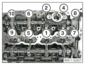
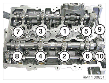
- Loosen all screws on the intake camshaft bearing caps in sequence from (10) to (1).
- Take off intake camshaft bearing caps (E1), (E2), (E3), (E4) and (E) and place them in order in the special tool 0 495 105 (11 4 480)
.
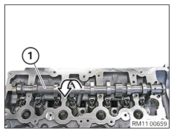
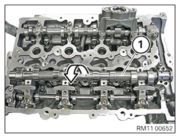
- Remove the intake shaft (1) in the direction of the arrow.
Remove the servomotor for the eccentric shaft (cylinder head removed)
Additional information is available.
Electrostatic discharge.
Damage to or destruction of electrical components.
- Leave electrical components in original packaging until just before they are installed. Use the original packaging only for any return shipments. Always package removed components straight away.
- Read and comply with user information on using the associated special tool 12 7 060.
- Only touch the housings of electrical components. Do not touch pins or multi-pin connectors directly.
- Wear electrically conductive clothing and antistatic shoes (with ESD symbol).
- For additional information see: 61 35... NOTES ON ESD (ELECTROSTATIC DISCHARGE) PROTECTION
- Loosen screws (1).
- Adjust servomotor (3) for the eccentric shaft slowly to the minimum lift using a standard hexagon socket wrench (2) of 4 mm
in the direction of the arrow.
This releases the tension of the eccentric shaft.
Do not turn the eccentric shaft beyond the end stop.
- Guide out and remove servomotor (3) for the eccentric shaft.
Remove eccentric shaft
- Release screws (1) and set down the bearing cap neatly in special tool 0 495 105 (11 4 480) .
- Release screws (2) and set down the bearing support neatly in special tool 0 495 105 (11 4 480) .
- For an engine that has been in use, make sure all bearing supports are reinstalled in the same position.
- Remove eccentric shaft (1) in direction of arrow.
Remove exhaust camshaft.
- Subsequently ensure that the exhaust camshaft bearing cap is placed in 0 495 105 (11 4 480)
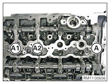
in the special tool.NOTE: The exhaust camshaft bearing caps are legibly labelled from the intake side and marked with A1, A2 and A.NOTE: Exhaust camshaft bearing cap A is a thrust bearing.
- Loosen all screws on the exhaust camshaft bearing cap in sequence from (10) to (1) in half turn.
- Drop the exhaust camshaft bearing cap (A1), (A2) and (A) and place in order in the special tool 0 495 105 (11 4 480)
.
- Remove the roller tappet (1).
- Remove the high pressure pump bracket (2).
- Remove the exhaust camshaft (1) in the direction of the arrow.
Remove all roller cam followers
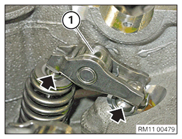
- Detach and remove the roller cam followers (1) on the intake side from hydraulic valve clearance compensating elements (arrows).
- Place all the roller cam followers (1) in order in the special tool 0 495 105 (11 4 480)
.
- Detach and remove the roller cam followers (1) on the output side from hydraulic valve clearance compensating elements (arrows).
- Place all the roller cam followers (1) in order in the special tool 0 495 105 (11 4 480)
.
Removing all hydraulic valve clearance compensating elements
- Remove all hydraulic valve clearance compensating elements (1) in the direction of arrow to the top.
- Place hydraulic valve clearance compensating elements (1) together with the rocker arms, orderly into the special tool 0 495 105 (11 4 480)
.
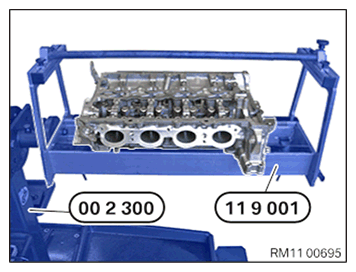
Remove all valve springs
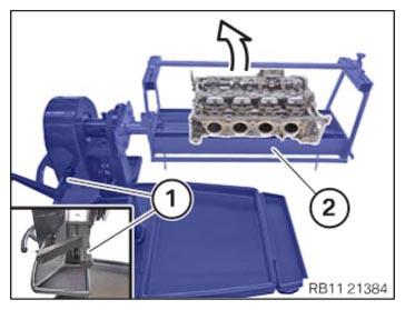
- Mount and bolt special tool 0 494 366 (11 9 001) on special tool 0 495 187 (00 2 300) .
- Mount and bolt the cylinder head to the special tool 0 494 366 (11 9 001)
.
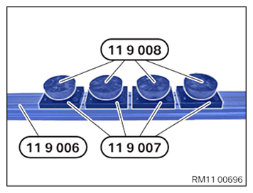
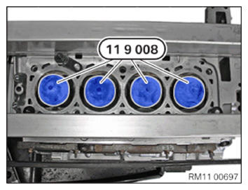
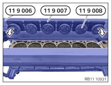
- Prepare the special tools 0 494 371 (11 9 006), 0 494 372 (11 9 007)
and 0 494 373 (11 9 008)
as shown.
- Make sure that the special tools 0 494 373 (11 9 008)
are positioned as shown in the next operation.
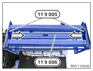
- Turn round special tool 0 494 371 (11 9 006) and insert as shown.
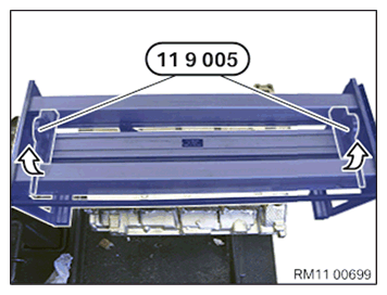
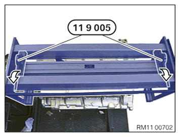
- Slide the special tool 0 494 370 (11 9 005)
in the direction of the arrow.
- Lock special tool 10 494 370 (11 9 005) in the direction of the arrow.
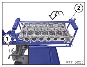
- Rotate the cylinder head with the special tool 0 494 362 (11 9 000)
by 180° into the installation position.
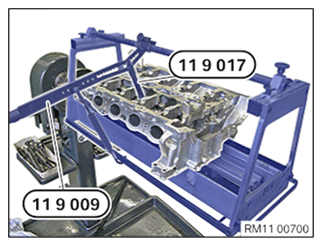
- Align special tool 0 494 374 (11 9 009)
in direction of valve axis.CAUTION: Component with preload.
Danger of injury!- Reduce preload as far as possible before disassembly. Relieve component.
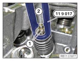
- Press down the valve spring on the upper spring cup with the special tools 0 494 374 (11 9 009) and 0 495 028 (11 9 017) .
- Keep the valve spring pressed down with the special tool 0 495 028 (11 9 017) .
- Remove the valve shims (1) with a magnet from the valve (2).
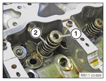
- Carefully relieve the valve spring.
- Set the spring cup (1) and the valve spring (2) down in the special tool 0 495 105 (11 4 480)
in order.
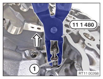
Remove valve stem seals
NOTE: RISK OF DAMAGE
Contaminant or foreign body.
Contamination can result in malfunctions, operating failure or leaks.- Adhere to the utmost cleanliness.
- Protect components from contamination e.g. by covering.
- Close off line connections with seal plugs.
NOTE: The description is for one component only. The procedure is identical for all further components. - Remove valve stem seal (1) using special tool 0 490 796 (11 1 480)
in the direction of the arrow.
Remove all valves
NOTE: RISK OF DAMAGE
Contaminant or foreign body.
Contamination can result in malfunctions, operating failure or leaks.- Adhere to the utmost cleanliness.
- Protect components from contamination e.g. by covering.
- Close off line connections with seal plugs.
- B46/B48:
Rotate the special tool 0 494 366 (11 9 001) (2) on the crank (1) by 180° in the direction of arrow .
- B58t:
Rotate the special tool 0 494 366 (11 9 001) (2) on the crank (1) by 180° in the direction of arrow.
- Unlock the special tools 0 494 370 (11 9 005)
in the direction of the arrow.
- B46/B48:
Remove special tools 0 494 373 (11 9 008) if necessary.
- B58t:
Thread out and remove special tools 0 494 371 (11 9 006) , 0 494 372 (11 9 007) and 0 494 373 (11 9 008) in direction of arrow.
- Slide the valve stem (1) in the direction of arrow
in the cylinder head.
- Remove the valve (1) and position in special tool 0 495 105 (11 4 480)
in order.