Removing the torsion springs (cylinder head removed)
Further information is available.
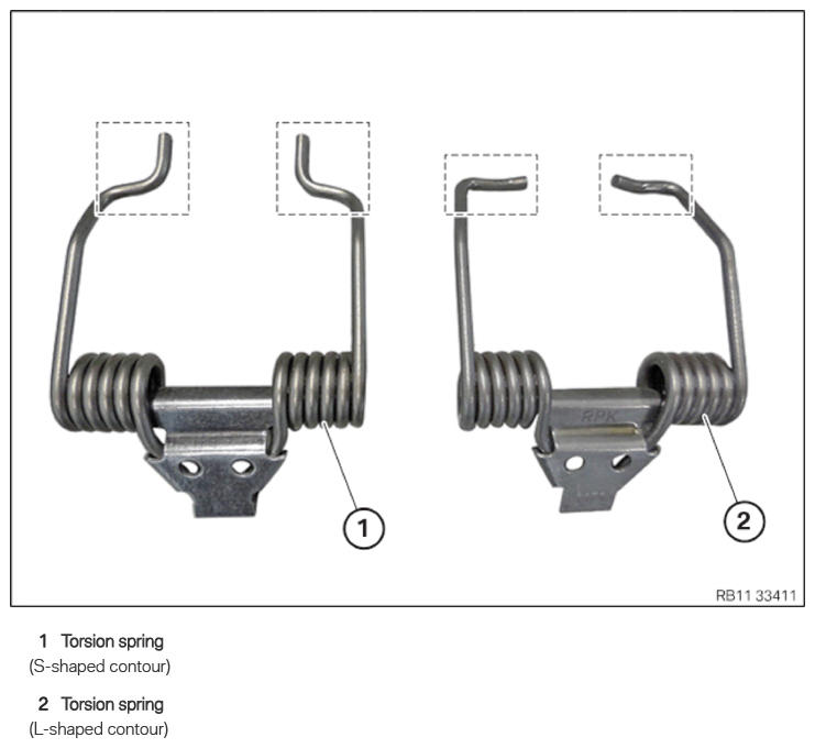
Torsion spring
Injury hazard!
- The use of the specified special tool (tool) is mandatory.
- Carry out the described steps properly.
Wear safety goggles.
For disassembly and installation of the torsion spring, special tool 2 359 088 is used. Due to technical modifications in the torsion spring, special tool 5 A0B 120 is mounted on the existing special tool 2 359 088 .
Information on modification can be found in the additional information.
Alternative to the new special tool 5 A24 F30 , the already known special tool SWZ: 2 359 088 can be used in modified form.
Information on modification can be found in the additional information.
The modified special tool is upward compatible.
When replacing one or more torsion springs:
When removing the torsion spring, it is imperative to note the part number of the torsion spring.
A mixed installation of torsion springs is only permitted in combination with the appropriate intermediate lever.
For further information on possible combinations, see the applicable BMW parts catalogue.
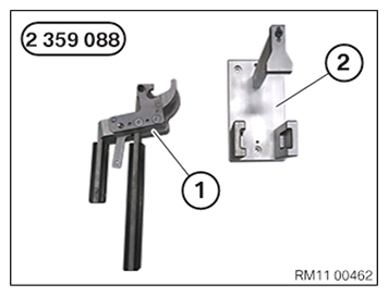
- Keep a set of special tools 2 359 088
for removing the torsion spring with an s-shaped contour ready:
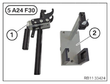
Number Description 1 Clamping lever 2 Mount for clamping lever (for torsion spring with s-shaped contour) - Keep a set of special tools 5 A24 F30
or, alternatively, the modified special tool 2 359 088
for removing the torsion spring with an L/s-shaped contour ready:
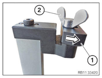
Number Description 1 Clamping lever 2 Mount for clamping lever (for torsion spring with L-/s-shaped contour) - Version with a torsion spring with an S-shaped contour with special tool 5 A24 F30 or the modified special tool 2 359 088:
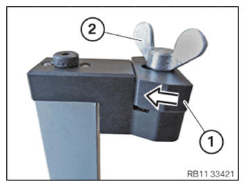
Bring the shaped part (1) in arrow direction onto the contact surface.
Turn wing screw (2) until hand-tight.
- Version with a torsion spring with an L-shaped contour with special tool 5 A24 F30 or the modified special tool 2 359 088:
Bring the shaped part (1) in arrow direction onto the contact surface.
- Turn wing screw (2) until hand-tight.
Checking the position of the intake camshaft (cylinder head removed)
Check
- Check position of the intake camshaft on the respective cylinders.
Result
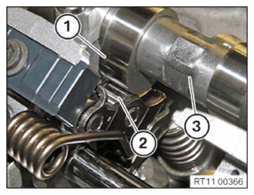
» Cam (1) of the intake camshaft runs on the intermediate lever (2).
Measure
- Continue turning intake camshaft (3) with a conventional open-end wrench until the cam (1) does not run on the intermediate lever (2).
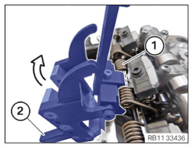
- Open the clamping lever and position it on torsion spring (1).
- Position the snap-in hooks (2) in arrow direction
.
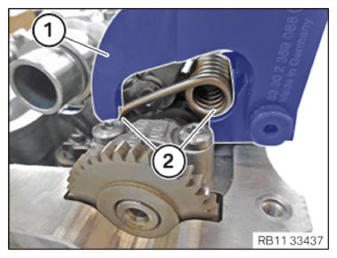
- Make sure that the torsion spring (2) is correctly positioned in the clamping lever (1).
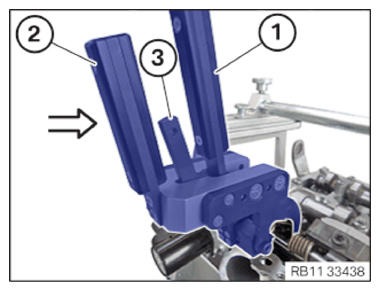
- Hold down lever (1).
- Close the lever (2) carefully in arrow direction
until the snap-in hooks (3) engage audibly.
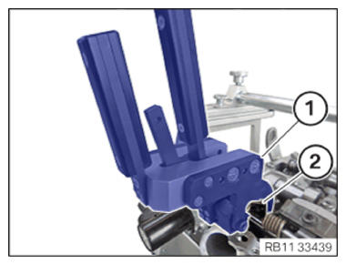
- Carefully
guide out and remove clamping lever (1) with the preloaded
torsion spring (2).
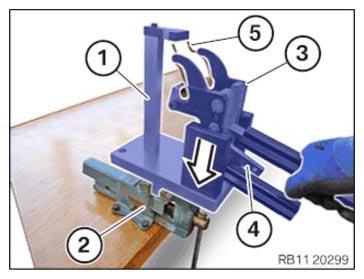
- Clamp mount (1) in vice (2).
- Position the clamping lever (3) with the preloaded torsion spring (5) in arrow direction in the mount (1).
Snap-in hooks (4) of clamping lever (3) are used to relax clamping lever (3).
Relax the torsion spring (5) with that.
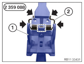
- Version with a torsion spring with an s-shaped contour and the special tool 2 359 088:
Unlock the clamping lever (1) of the special tool 2 359 088 carefully in the associated mount.
Make sure that the torsion spring (2) while correctly lies in the lateral guides (arrows) and the mark of the clamping lever (1) while relaxing.
Place torsion spring (2) properly in special tool 0 495 105 (11 4 480) .
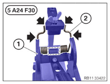
- Version with a torsion spring with an S-shaped contour and special tool 5 A24 F30 or the modified special tool 2 359 088:
Unlock the clamping lever (1) of the special tool 5 A24 F30 or of the modified special tool 2 359 088 in the associated mount carefully .
Make sure that the torsion spring (2) lies correctly in the lateral guides (arrows) and the mark of the clamping lever (1) while relaxing.
Place torsion spring (2) properly in special tool 0 495 105 (11 4 480) .
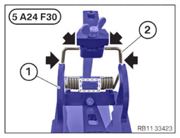
- Version with a torsion spring with an L-shaped contour and special tool 5 A24 F30 or the modified special tool 2 359 088:
Unlock the clamping lever (1) of the special tool 5 A24 F30 or of the modified special tool 2 359 088 in the associated mount carefully .
Make sure that the torsion spring (2) lies correctly in the lateral guides (arrows) and the mark of the clamping lever (1) while relaxing.
Place torsion spring (2) properly in special tool 0 495 105 (11 4 480) .
- Repeat the steps for the remaining torsion springs.