Installing all gates
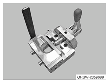
- Have the special tool 2 359 089
ready.
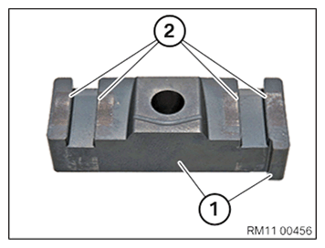
- Clean contact surfaces (1) and (2) off oil, grease and dirt.
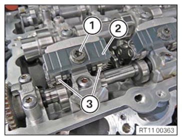
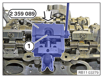
- Fit the gate (2) and hand-tighten the screw (1).
- Make sure the intermediate lever (3) is in the correct installation position.
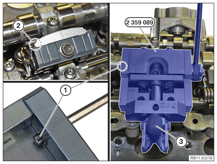
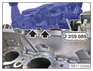
- Position the special tool 2 359 089 on the cylinder head.
- Pre-tension the gate with the lever (3).
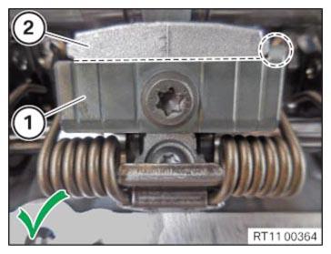
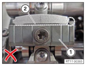
- Bring the screw (1) onto the contact surface in the area (2).
- Make sure that the special tool 2 359 089
does not rotate during this process.
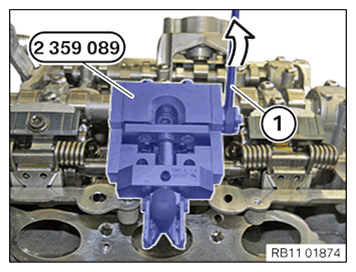
- Attach the gate with the lever (1) in arrow direction.
- Make sure that the special tool 2 359 089
rests flat against the cylinder head (arrows).
- Press the special tool 2 359 089 in arrow direction onto the cylinder head. Simultaneously tighten the screw (1).
TIGHTENING TORQUES SPECIFICATION
| Gate to bearing bracket | ||
| M7 | Tightening torque | 20 Nm |
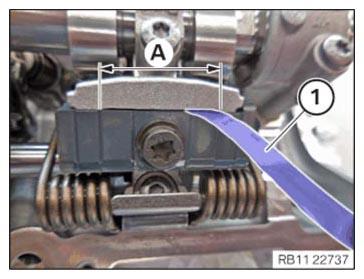
- Check the conventional gauge (1) in the area (A) for the correct gap dimension.
TECHNICAL DATA - GAP DIMENSION SPECIFICATION
| Gap dimension between gate and bearing bracket | |
| Gap dimension A | 0.03 mm |