Check compression of all cylinders
WARNING:
Hot surfaces.
Risk of burning!
Risk of burning!
- Perform all work only on components that have cooled down.
Preliminary work:
- Refer to REMOVING THE ACOUSTIC COVER .
- Refer to WHEN WORKING ON THE LAST CYLINDER: RELEASING THE SERVICE OPENING IN SOUND INSULATION ON TOP OF ENGINE .
- Refer to REMOVING THE IGNITION COILS .
- Refer to REMOVING ALL SPARK PLUGS .
- Refer to DISCONNECTING THE CONNECTOR A46*6B FROM THE CONTROL UNIT .
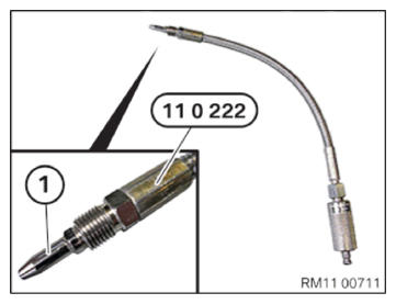
- Unscrew sensor (1) from special tool 0 490 615 (11 0 222) .
- Check the secure fit of the valve below.
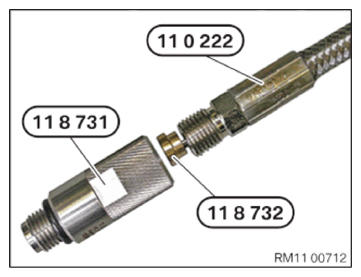
- Prepare special tool 0 490 615 (11 0 222) in conjunction with the special tool 0 496 306 (118 732) and 0 496 107 (11 8 730) .
- Screw special tool 0 490 615 (11 0 222)
with 10 Nm
on the special tool 0 496 107 (11 8 730).
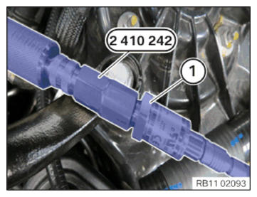
- Connect special tool 2 410 242 to special tool 0 490 613 (11 0 220) with the bayonet closure.
- 100-barsensor
100-bar sensor
100-barsensor
81 31 2 357 801
(1) Screw hand-tight into special tool 2 410 242.
- 100-barsensor
100-bar sensor
100-barsensor
81 31 2 357 801
(1) Connect with the IMIBR2
IMIBR2
IMIBR2
81 38 2 295 937
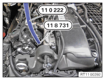
- Manually screw the special tool 0490 615 (11 0 222) with the special tool 0 496 305 (11 8 731)
into the spark plug thread.
- Observe diagnosis instructions.
Follow-up work:
- Refer to CONNECTING CONNECTOR A46*6B TO THE CONTROL UNIT .
- Refer to INSTALLING ALL SPARK PLUGS .
- Refer to INSTALLING IGNITION COILS .
- Refer to WHEN WORKING ON THE LAST CYLINDER: MOUNTING THE SERVICE OPENING IN THE SOUND INSULATION ON TOP OF THE ENGINE .
- Refer to INSTALLING ACOUSTIC COVER .