Removing the engine from the front subframe
CAUTION:
Heavy component.
Heavy components can lead to injury or damage.
Heavy components can lead to injury or damage.
- Remove and install heavy components with the aid of another person/other persons.
Preliminary work:
- Refer to REMOVING THE ACOUSTIC COVER OF THE OIL SUMP .
- Refer to REMOVING STARTER MOTOR (2017-2020) or REMOVING STARTER MOTOR (2021-2022) .
- Refer to REMOVING THE ENGINE FROM THE AUTOMATIC TRANSMISSION (LIFTING TABLE) .
CAUTION:
Components connected to the engine joint or cross member.
Injury hazard!
Injury hazard!
- Check lifting eyes and engine mounting brackets for damage, e.g. cracks.
- Attach the component to correctly mounted engine joints or cross members only.
- Only lift the component, do not shift it forwards, backwards or in transverse direction.
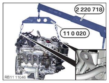
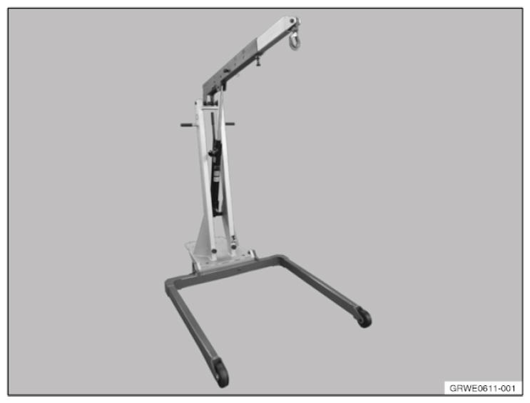
- Stage the workshop crane 2 220 718
.
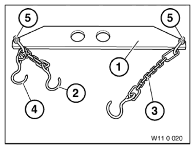
- Stage the lifting gear 0 490 567 (11 0 020)
.
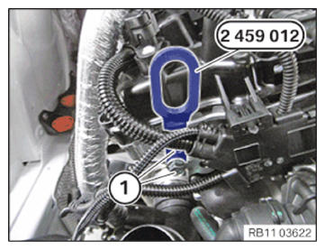
- Insert and position the special tool 2 459 012 at the cylinder head.
- Tighten the screws (1) of the special tool 2 459 012 .
TIGHTENING TORQUES SPECIFICATION
| Special tool to cylinder head | ||
| M8 | Tightening torque | 21.5 Nm |
NOTE:
TECHNICAL INFORMATION
The workshop crane, lifting gear and the mounting brackets on the engine must all be connected to each other so that the engine hangs straight upon lifting.
The workshop crane, lifting gear and the mounting brackets on the engine must all be connected to each other so that the engine hangs straight upon lifting.
- Connect both hooks of the special tool 0 490 567 (11 0 020) to the front and rear of the engine with the mounting brackets.
- Connect the workshop crane 2 220 718
to the special tool 0 490 567 (11 0 020)
.
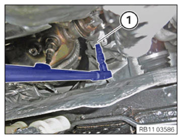
- Release the screw (1) on the left and right engine mount with a standard tool.
- Lift and remove the engine with the workshop crane 2 220 718
.
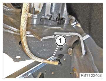
- Version engine mount with vacuum line:
- Loosen the vacuum line (1).