Removing the engine from the front subframe
CAUTION:
Heavy component.
Heavy components can lead to injury or damage.
Heavy components can lead to injury or damage.
- Remove and install heavy components with the aid of another person/other persons.
Preliminary work:
- Refer to REMOVING THE FRONT OUTPUT SHAFTS (ON THE MOBILE LIFTING TABLE) .
- Refer to REMOVING THE ACOUSTIC COVER OF THE OIL SUMP .
- Refer to REMOVING STARTER MOTOR .
- Refer to REMOVING THE ENGINE FROM THE AUTOMATIC TRANSMISSION (LIFTING TABLE)
CAUTION:
Components connected to the engine joint or cross member.
Injury hazard!
Injury hazard!
- Check lifting eyes and engine mounting brackets for damage, e.g. cracks.
- Attach the component to correctly mounted engine joints or cross members only.
- Only lift the component, do not shift it forwards, backwards or in transverse direction.
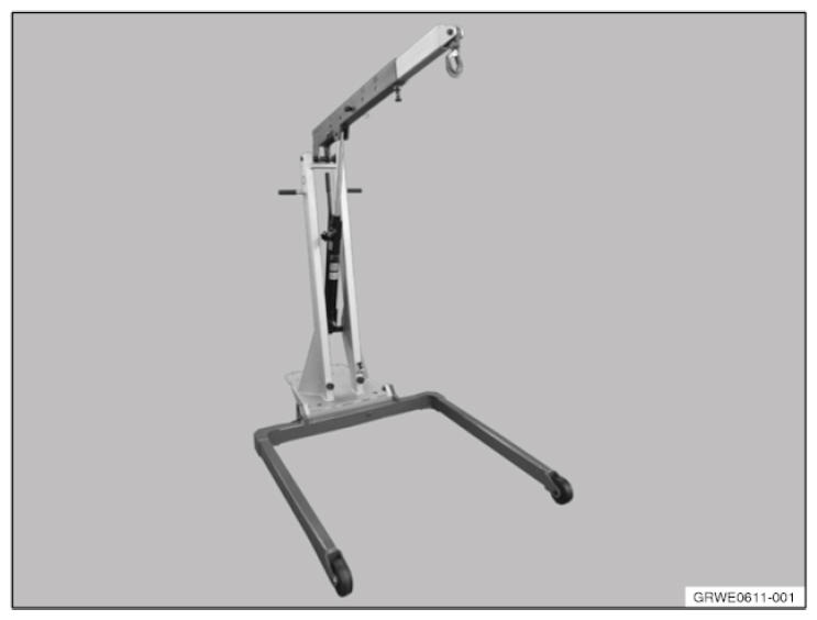
- Stage the workshop crane 2 220 718.
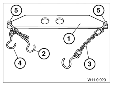
- Stage the lifting gear 0 490 567 (110 020).
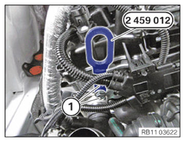
- Insert and position the special tool 2 459 012 at the cylinder head.
- Tighten the screws (1) of the special tool 2 459 012. TIGHTENING TORQUES SPECIFICATION
Special tool to cylinder head M8 Tightening torque 21.5 Nm NOTE: TECHNICAL INFORMATION
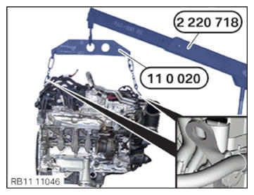
The workshop crane, lifting gear and the mounting brackets on the engine must all be connected to each other so that the engine hangs straight upon lifting. - Connect both hooks of the special tool 0 490 567 (11 0 020) to the front and rear of the engine with the mounting brackets.
- Connect the workshop crane 2 220 718 to the special tool 0 490 567 (11 0 020).
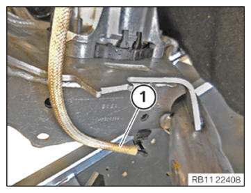
- Release the screw (1) on the left and right engine mount with a standard tool.
- Lift and remove the engine with the workshop crane 2 220 718.
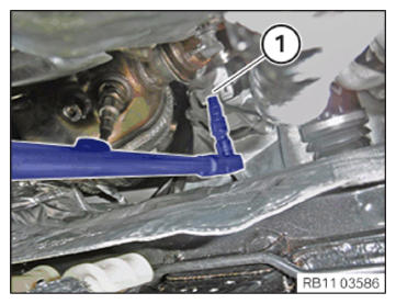
- Version engine mount with vacuum line:
- Loosen the vacuum line (1).