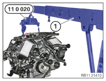
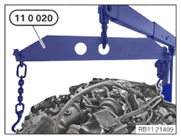
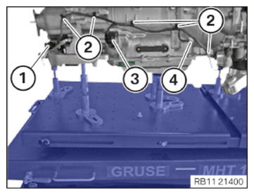
Attaching the engine to the lifting table
- Lift the engine with a workshop crane (1) and the special tool 0 490 567 (11 0 020)
into the engine mounts.
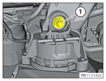
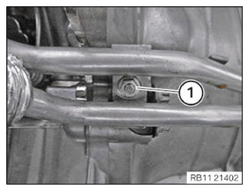
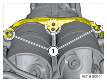
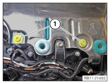
- Tighten down screw (1).
| Engine mount to engine support bracket | ||
| Screw M12x1.5x40 | Tightening torque | 100 Nm |
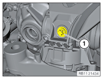
- Tighten down screw (1).
| Engine mount to engine support bracket | ||
| Screw M12x1.5x40 | Tightening torque | 100 Nm |
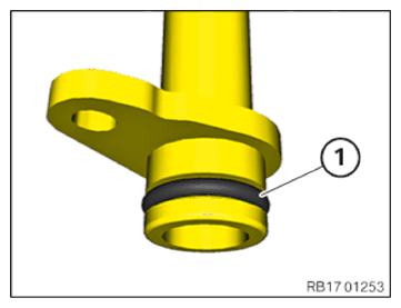
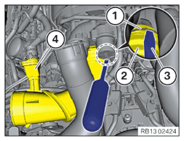
- Replace the O-rings (1) on the lines of the engine oil cooler.
Parts: O-rings
- Coat the O-rings (1) with engine oil.
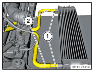
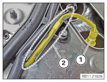
- Variant with coolant radiator:
Position the coolant lines (2).
NOTE: Collect and dispose of emerging fluids. Observe country-specific waste disposal regulations. - Tighten nuts (1).TIGHTENING TORQUES SPECIFICATION
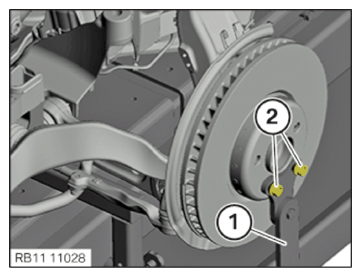
Line on upstream coolant radiator (engine oil cooler) Nut M8 tightening torque 18 Nm - Loosen screws (2).
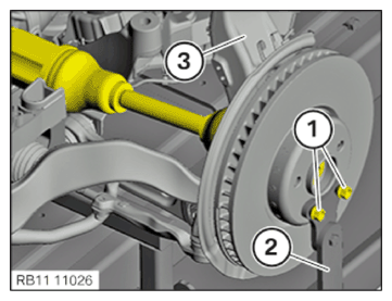
- Remove the swivel bearing mount (1) and set it aside.
- Hold the swivel bearing with the special tool 2 220 718.
Check
- Replace the circlip (1).
Parts: Circlip
- Coat the contact surface (2) of the output shaft with the recommended front axle transmission oil, see additional information.
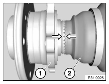
- Check the gearing for damage or deformation.
Result
» The gearing is deformed or damaged.
Measure
- Replace the output shaft.
Parts: Output shaft
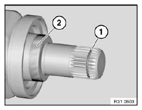
- Clean and degrease front gearing of wheel bearing (1) and output shaft (2).
- Install front gearing of wheel bearing (1) and output shaft (2) and establish a positive connection.
- By twisting of both the wheel hub and the output shaft in arrow direction, ensure that the front gears engage in each other.
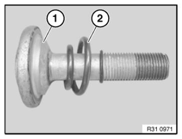
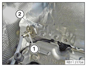
- Replace the screw (1) and the compression spring (2).
Parts: Screw, compression spring
- Clean and degrease the screw (1).
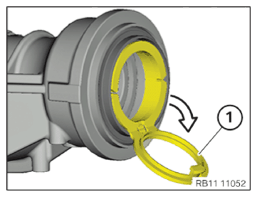
- Observe the installation position of the compression spring (2)!NOTE: Radial shaft seal ring are equipped with an installation protection ring. The installation protection ring is used to protect the sealing lip when installing the output shaft.
- Open the installation protection ring (1) in arrow direction before installing the output shaft.
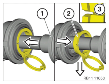
- Feed in the output shaft (1) in the direction of the arrow.
- Release the installation protection ring (2) and feed it out a little.
- Pull the assembly protection ring (2) down with force in arrow direction until the predetermined breaking points (3) on the assembly protection ring break.
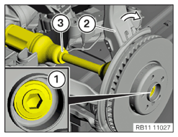
- Install the stand (2) of the swivel bearing (3).
- Hand-tighten the screws (1).
- Tilt the swivel bearing (2) slightly forwards in the direction of the arrow.
- Insert the output shaft (3) into the front axle differential until the stop is reached and until you can feel the output shaft (3) engaging noticeably.
- Tighten screw (1) with the special tool 0 490 504 (00 9 120). TIGHTENING TORQUES SPECIFICATION
Output shaft to wheel bearing M16 Replace collar screw and spring. Joining torque 210 Nm Angle of rotation 90° - Variant with sealing cap:
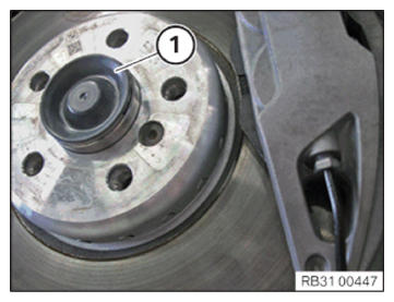
Attach the sealing cap (1).
Checking lining sleeves
- Check the fitting sleeves (1) for correct seating and damage and replace if necessary.
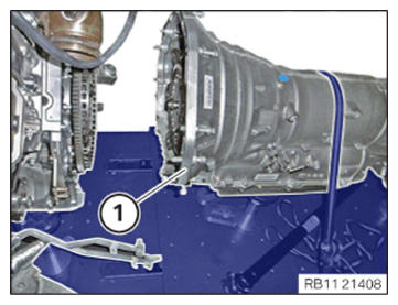
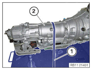
- Slide transmission (1) to the front and position at the engine.
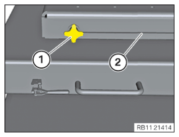
- Apply retaining screws (1) on the lifting table (2) on both sides hand-tight.
Flange-mount transmission
- Transmission flange-mount.
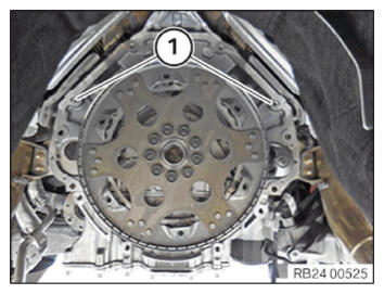
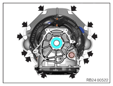
- Rotate torque converter until bore in torque converter is flush with bore in drive plate.
- Join and tighten the transmission bolts (arrows).TIGHTENING TORQUES SPECIFICATION
Transmission to engine M8 tightening torque 19 Nm M10 tightening torque 38 Nm Remove the special tool from the torque converter
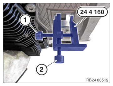
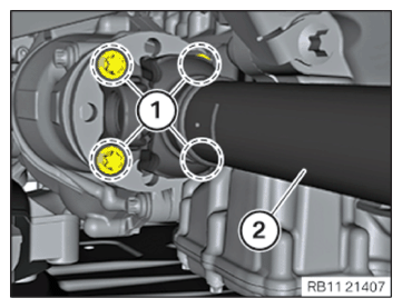
- Release the screws (1) and (2).
- Remove the special tool 0 494 451 (24 4 160).
- Replace screws (1).
Parts: Screws
- Screw the torque converter onto the vertically arranged elongated hole.
It is compulsory to screw the torque converter onto the vertically arranged elongated hole first.
- Rotate the torque converter until the elongated hole is visible in the opening.
- Tighten down screw (1).
| Torque converter to flywheel | ||
| M10 Replace screws. |
tightening torque | 60 Nm |
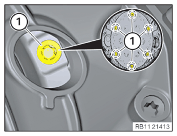
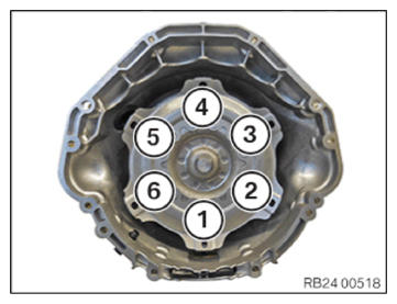
- Turn the crankshaft at central bolt only in clockwise direction.
- Observe the tightening sequence of the additional five screws (torque converter on flywheel)
compulsorily:
Tightening sequence: 4 - 3 - 6 - 5 - 2
The screw connection (1) is the vertically arranged elongated hole in the torque converter.
TIGHTENING TORQUES SPECIFICATIONTorque converter to flywheel M10
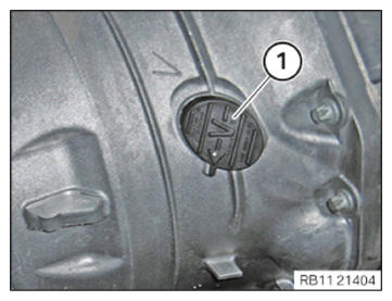
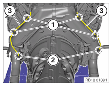
Replace screws.tightening torque 60 Nm - Install the cover (1).
- Position the front prop shaft (2).
- Replace screws (1).
Parts: Screws
- Tighten down screws (1).TIGHTENING TORQUES SPECIFICATION
Prop shaft before the front axle differential Replace screws.
Joining torque and angle of rotation must be observed without fail.Joining torque 20 Nm Angle of rotation 45° - Detach the engine on the engine mounting bracket with a workshop crane and special tool 0 490 567 (11 0 020).
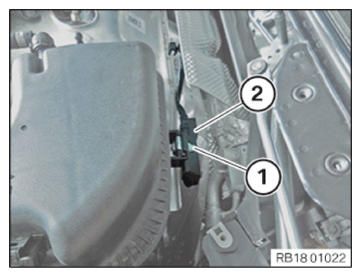
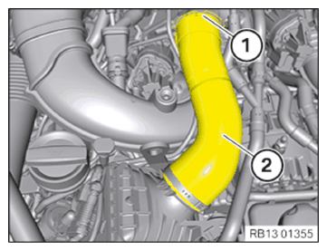
- Using suitable screwdrivers (3), unclip the retaining clips (1) upwards from the surrounding guides (2).
Retaining the retaining clips (1) in the unlocking position is not possible due to the design.
- Remove clean air pipe of bank 1 (4).NOTE: Check the plastic components of the locking mechanism or clamp for damage.NOTE: Replace the charge air ducts with damaged plastic components on the locking mechanism.
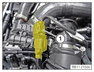
- Connect the right charge air line (2) to the exhaust turbocharger.
- Lock the lock (1) audibly.
- Replace sealing rings.
Parts: Sealing ring
- Install the hydraulic lines (1) on the transmission in the arrow direction.
- Position and tighten the screw (2).
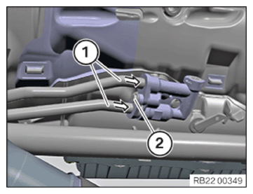
| Transmission oil line to transmission | ||
| M6x25 Replace the sealing ring. |
tightening torque | 8 Nm |
- Tighten nut (1).
| Transmission oil line to transmission | ||
| M6x25 Replace the sealing ring. |
tightening torque | 8 Nm |
- Release the cargo straps (1) from the transmission (2).
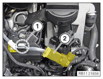
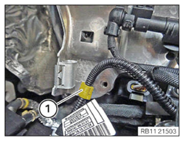
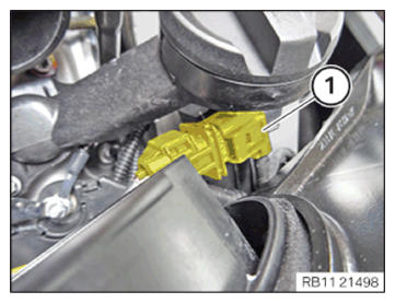
- Connect connectors (1) and lock.
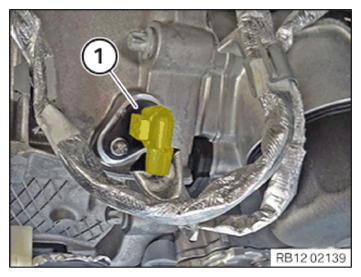
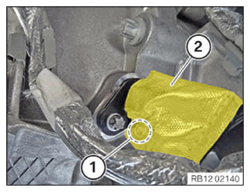
- Lock the thermal protection (2) at the push-button (1).
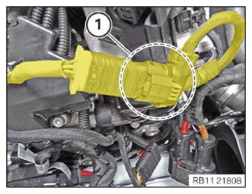
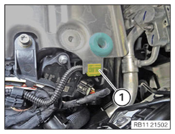
- Connect the connector (1) to the transfer box (TB) and lock it.
- Fix wiring harness fasteners (2).
- Connect connector (3) on the automatic transmission and lock it.
- Remove ground cable.
- Tighten down screw (4).
| Ground connection on transmission | ||
| M6x12 screw | Tightening torque | 10 Nm |
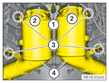
- Feed in and install the catalytic converters (3).
- Loosen nuts (1).
| Catalytic converter to holder | ||
| M8 Nut Replace nut. |
tightening torque | 23 Nm |
- Loosen screws (2).
| Catalytic converter to holder | ||
| M8x20 Replace screw. |
tightening torque | 19 Nm |
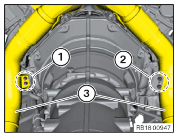
- Replace the circlips (2).
Parts: Clamps
- Mount the circlips (2) and tighten the screws (1).
The circlips (2) must be mounted with the screw connection inwards.
TIGHTENING TORQUES SPECIFICATIONCatalytic converter to exhaust turbocharger cl
Replace clamp after disassembly.Tightening torque 14 Nm - Tighten the screws (3) on the catalytic converters (4).TIGHTENING TORQUES SPECIFICATION
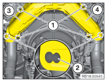
Catalytic converter on cylinder head/cylinder head cover/holder M8x20 tightening torque 21 Nm - Feed in the heat shield (3) and (4) at the retaining tabs (2).
- Tighten down screws (1).TIGHTENING TORQUES SPECIFICATION
Heat protection plate M6x16 tightening torque 10 Nm - Tighten down screws (1).TIGHTENING TORQUES SPECIFICATION
Heat protection plate M6x16 tightening torque 10 Nm - Variant with a gasoline particulate filter:
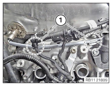
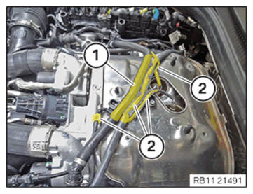
Clip pressure lines (3) into the retaining clips in areas (1).
Tighten union nuts (2).
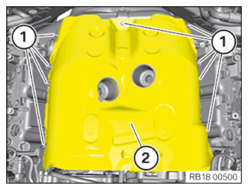
TIGHTENING TORQUES SPECIFICATIONPressure line to catalytic converter near engine Pressure line Tightening torque 20 Nm - Position the top heat shield (2).
- Tighten down screws (1).TIGHTENING TORQUES SPECIFICATION
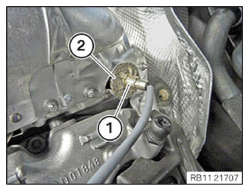
Heat protection plate M6x16 tightening torque 10 Nm - Position oxygen sensor monitor probe.
- Tighten the oxygen sensor monitor with the special tool 0 491 074 (11 7 020). TIGHTENING TORQUES SPECIFICATION
Front Lambda oxygen sensor/oxygen sensor monitor on catalytic converter M18x1.5 tightening torque 50 Nm - Push on the heat protection wire ring (2) until the stop is reached.
- Affix the retaining clip (1).
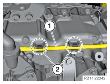
- Clip cable of oxygen sensor control probe into holder (1).
- Clip cable of oxygen sensor monitor probe into the clamps (1).
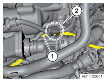
- Connect connectors (1) and lock.
- Clip cable of oxygen sensor monitor probe into the clamp (1).
- Slide the plug connector backwards to the stop.
- Install and tighten the oxygen sensor monitor using the special tool 0 491 074 (11 7 020). TIGHTENING TORQUES SPECIFICATION
Front Lambda oxygen sensor/oxygen sensor monitor on catalytic converter M18x1.5 tightening torque 50 Nm - Cover the heat protection wire ring (2) over the oxygen sensor monitor.
- Clip in the retaining clip (1).
- Clip in the cable (1) of the oxygen sensor monitor in the holders (2).
- Clip in the cable (1) of the oxygen sensor monitor in the holders (2).
- Clip in the cable (1) of the oxygen sensor monitor in the holders (2).
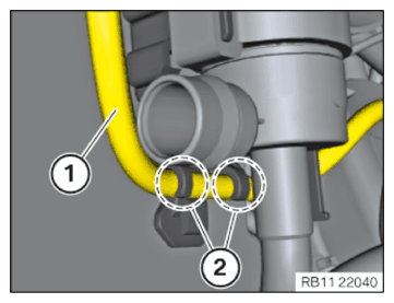
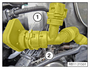
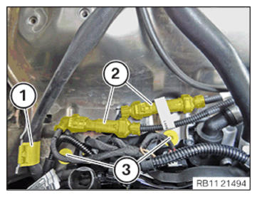
- Pass the connector (2) of the oxygen sensor monitor under the engine ventilation line (1).
- Connect connectors (1) and lock.
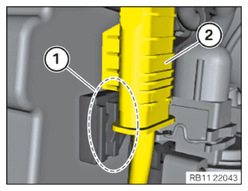
- Slide the plug connection of the oxygen sensor monitor (2) downwards in area (1) and secure.
- Attach the holder in the area (1) to the charge air cooler (2).
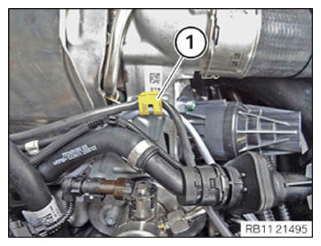
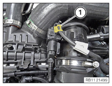
- Connect the quick-release coupling (1) and lock.
- Clip in the wiring harness mounting (1) at the heat shield.
- Clip in the wiring harness mounting (1) at the heat shield.
- Clip in the connector (2) downwards in the heat shield.
- Clip the transmission wiring harness on to the bracket (1).
- Tighten the screws (3).TIGHTENING TORQUES SPECIFICATION
Support bridge M6x16 screw Tightening torque 10 Nm - Tighten down screws (1).TIGHTENING TORQUES SPECIFICATION
Support bridge M6x16 screw Tightening torque 10 Nm - Tighten the oxygen sensor monitor at right (1) with the special tool 0 491 074 (11 7 020). TIGHTENING TORQUES SPECIFICATION
Front Lambda oxygen sensor/oxygen sensor monitor on catalytic converter M18x1.5 tightening torque 50 Nm - Secure the right Lambda oxygen sensor cable in area (2) in the cable bracket.
- Feed the connector (2) of the Lambda oxygen sensor through.
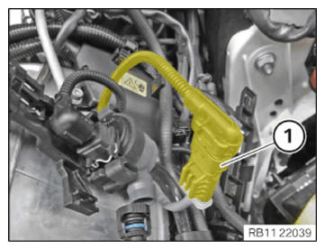
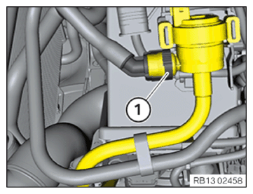
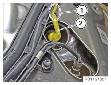
- Connect and lock the engine ventilation line to the retaining clip in the region of (1).
- Connect connectors (1) and lock.
- Clip the cable of the Lambda oxygen sensor into the holder (1).
- Tighten the oxygen sensor monitor at right (2) with the special tool 0 491 074 (11 7 020). TIGHTENING TORQUES SPECIFICATION
Front Lambda oxygen sensor/oxygen sensor monitor on catalytic converter M18x1.5 tightening torque 50 Nm - Fix the cable of the right Lambda oxygen sensor in the area (1) in the cable bracket.
- Guide in the right Lambda oxygen sensor and position.
- Connect connectors (1) and lock.
- Connect and lock the engine ventilation line to the retaining clip in the region of (1).
- Clip cable of oxygen sensor control probe into holder (1).
- Clip in the wiring harness from the attachment points (2).
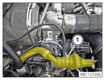
- Working downwards, clip in the engine ventilation line (1).
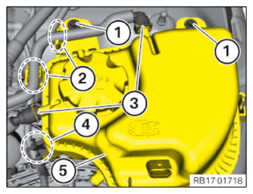
- Feed in and install coolant expansion tank (5).
- Tighten down screws (1).TIGHTENING TORQUES SPECIFICATION
Coolant reservoir M6x20 screw Tightening torque 11 Nm - Clip in wiring harness mounting (4).
- Clip the coolant ventilation line into the holders in the areas (2).
- Connect and lock the coolant ventilation lines (3).
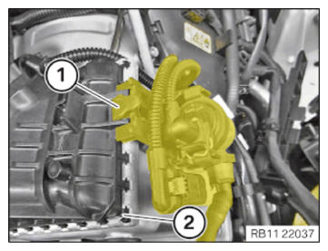
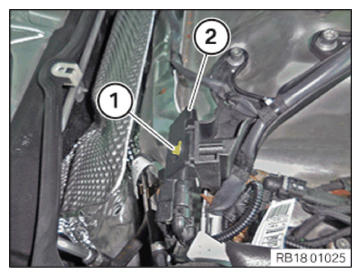
- Position the cover of the gasoline particulate sensor (2).
- Tighten down screw (1).TIGHTENING TORQUES SPECIFICATION
Gasoline particulate sensor to holder of cylinder bank 1 Plastic screw 6x18 Tightening torque 5.5 Nm - Position the cover of the gasoline particulate sensor (2).
- Tighten down screw (1).
| Gasoline particulate sensor to coolant expansion tank | ||
| M6x20 screw | Tightening torque | 8 Nm |