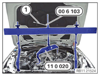
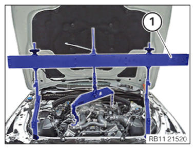
Remove engine bridge
- Lower the engine by 10 mm by turning the special tool 2 361 506 (00 6 103) (1) using the special tool 0 490 567 (11 0 020).
The fixtures of the engine mounts must be located in the engine support brackets.
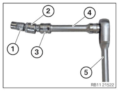
- Prepare tools:
- Torx socket E12
- Reduce from 1/2 inch to 3/8 inch
- Groove 12.5°
- Short extension of 1/2 inch
- 1/2" reversible ratchet
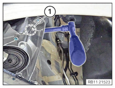
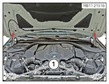
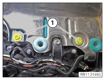
- Tighten the screw (1) of the left-hand engine mount using the prepared tool.TIGHTENING TORQUES SPECIFICATION
Engine mount to engine support bracket M12 tightening torque 100 Nm - Tighten the screw (1) of the right engine mount with a commercially available tool.TIGHTENING TORQUES SPECIFICATION
Engine mount to engine support bracket M12 tightening torque 100 Nm Remove the rear section of the wheel arch cover on the front left and right
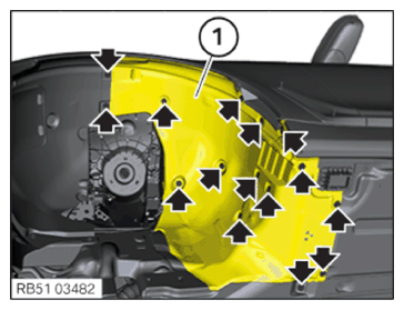
NOTE: Description is for left component only. Procedure on the right side is identical.Remove the rear section of the front wheel arch cover front
Further information is available.
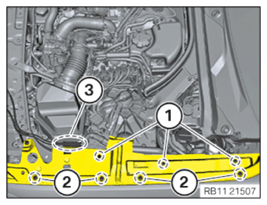
NOTE: To provide a better overview: Schematic diagram with partially hidden components. - Remove screws (arrows).
- Guide the wheel arch cover (1) out.
Install the cover of the steering assembly on the left and right
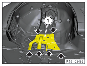
NOTE: Description is for left component only. Procedure on the right side is identical.Install the cover of the steering assembly
Further information is available.
NOTE: To provide a better overview: Schematic diagram with partially hidden components. - Insert the cover (1).
- Tighten all bolts (arrows).TIGHTENING TORQUES SPECIFICATION
Cover, steering unit Screw Tightening torque 3 Nm Install the front left and right wheels
Further information is available.
NOTE: Perform the steps on the left and right side.Mounting the wheel
Further information is available.
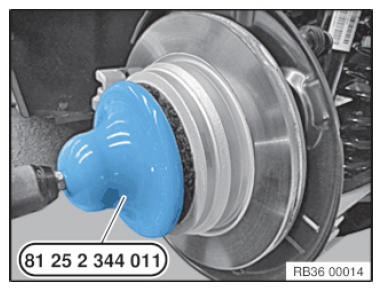
NOTE: The contact surface between the brake disc and the wheel rim must be clean and free from oil and grease. There is otherwise a risk of the wheel becoming loose at a later time. - Remove dirt, grease residues and corrosion from the contact surface with a drill and the special tool 2 344 011.
Do not operate special tool 2 344 011 with an impact screwdriver.
- Degrease the contact surfaces with the universal cleaner.
- In the event of grease residues in the area of the wheel bolt holes, remove and clean the brake disk.
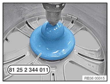
- Remove dirt, grease residues and corrosion from the contact surface with a drill and the special tool 2 344 011.
Do not operate special tool 2 344 011 with an impact screwdriver.
- Degrease the contact surfaces with the universal cleaner.
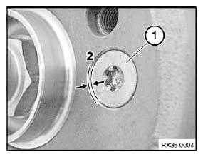
- Check if the mounting bolt (1) has been fitted correctly for the brake disk.
The mounting bolt (1) for the brake disk cannot protrude on the contact surface (2) between the brake disk and the rim.
| Brake disc to front wheel hub | ||
| M8 Replace screw. |
Tightening torques | 16 Nm |
| Brake disc to rear wheel hub | ||
| M8 Replace screw. |
Tightening torque | 16 Nm |
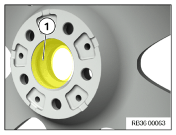
- Lightly grease the wheel centering (1) in the rim.CONSUMABLE - BRAKE BLOCKING PASTE DESCRIPTION
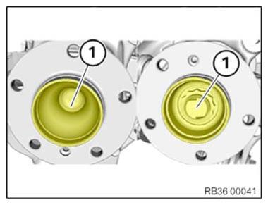
Brake block paste * TU = Trade Unit. TU numbers cannot be ordered! For invoicing purposes only. 3 g, Bag 83192158851 100 g, Tube 83192158852 5 g, TU* 83230140233 NOTE: Do not grease the wheel hubs and wheel centering in models G80, G82 and G83. - Apply a thin layer of grease to the front and rear wheel hubs (1) to protect against corrosion.CONSUMABLE - BRAKE BLOCKING PASTE DESCRIPTION
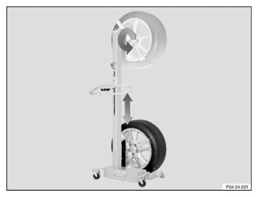
Brake block paste * TU = Trade Unit. TU numbers cannot be ordered! For invoicing purposes only. 3 g, Bag 83192158851 100 g, Tube 83192158852 5 g, TU* 83230140233 NOTE: A wheel lifter is recommended for easier wheel removal and installation without exertion. - In vehicles with M Carbon ceramic brake: The wheel lifter must be used to install the wheel.
This process is intended to prevent damage to the brake disc.
Check
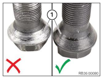
- Check lug bolts for wear.
Result
» Spots (> 30%) of the bearing surface (1) of the taper on the screw head show silvery wear.
Measure
- Replace lug bolts.
Parts: Lug bolts
NOTE: Never use an impact screwdriver or electric screwdriver to apply and tighten the lug bolts.
The rim must rest evenly against the brake disc.
In the case of non-original BMW lug bolts/wheel rims, it may be necessary to retighten the lug bolts on user account of setting properties (refer to the documentation from the manufacturer).
Do not apply oil to new lug bolts. - Replace the corroded lug bolts (arrows).
Parts: Lug bolts
- Clean wheel bolts (arrows).
- Check lug bolts (arrows) and threads for damage, replace lug bolts (arrows) if necessary.
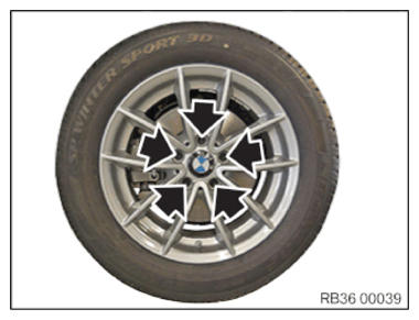
- Join and tighten the lug bolts (arrows).TIGHTENING TORQUES SPECIFICATION
Lug bolts M14/SW17 Screw in lug bolts and evenly tighten crosswise by hand in order to center the wheel rim.
Tighten lug bolts to the prescribed tightening torque with a calibrated torque wrench in a crosswise sequence.
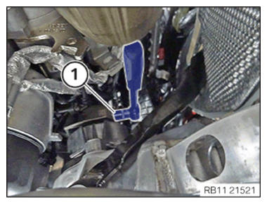
Check all the lug bolts in the same order or retighten to the prescribed tightening torque again.tightening torque 140 Nm Check 140 Nm - Detach the special tool 0 490 567 (11 0 020)
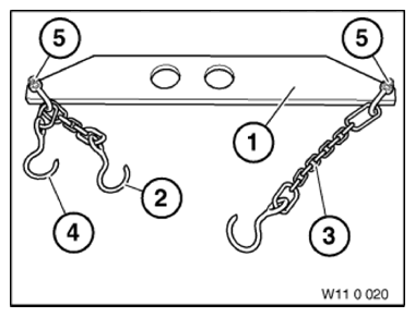
from the engine mounting brackets.NOTE: Conduct the following operation with the assistance of a second person.
- Remove the engine bridge (1) using the special tool 0 490 567 (11 0 020)
with the assistance of a support person.
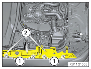
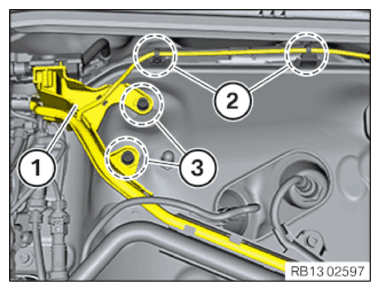
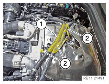
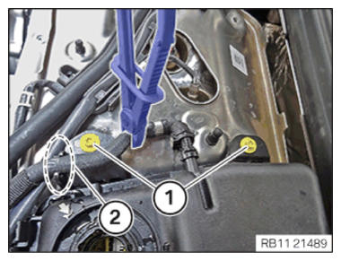
- Tighten the screws in the areas (1).TIGHTENING TORQUES SPECIFICATION
Top rear cross connection Torx screw M8x30 tightening torque 19 Nm Hexagon screw
M8x20tightening torque 19 Nm - Install the hood seal on the side (2).
- Install the expanding rivets (3).
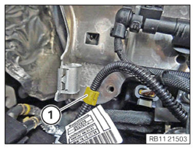
- Install the wiring harness mounting (1).
- Install the hood seal on the side (1).
- Install the expanding rivets (2).
- Install the side panel seal.
- Install the Bowden cables (3) out of the side panel sealing.
- Install clips (2).
- Install the expanding rivets (1).
- Install the sealing (2) of the side panel.
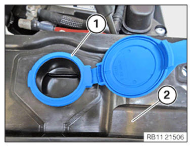
- Install the lid (1) of the washer fluid reservoir downwards.
- Install clips (2).
- Install the expanding rivets (1).
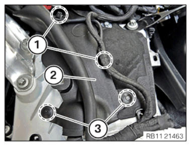
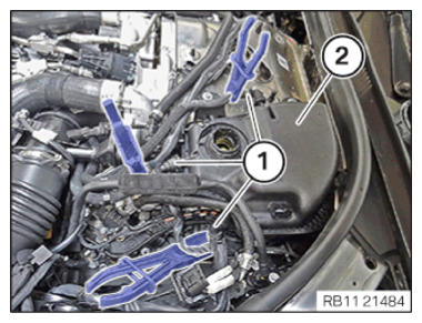
- Position heat shield.
- Clip in the wiring harness mounting (1) at the heat shield.
- Version with a gasoline particulate filter:
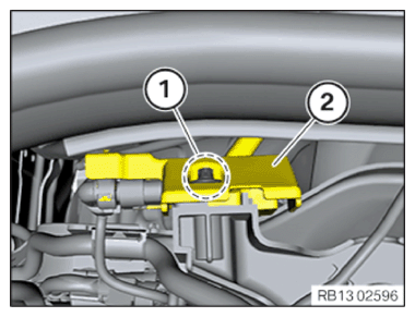
Position the holder of gasoline particulate sensor (2) with the gasoline particulate sensor (2).
Tighten down screw (1).
TIGHTENING TORQUES SPECIFICATIONGasoline particulate sensor to holder of cylinder bank 1 Plastic screw 6x18 Tightening torque 5.5 Nm - Version with a gasoline particulate filter:
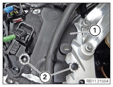
Position the holder (2) of the gasoline particulate sensor (1).
Tighten the screws (3).
TIGHTENING TORQUES SPECIFICATIONEngine wiring harness of transmission module to holder for expansion tank M6x16 screw Tightening torque 10 Nm - Version with a gasoline particulate filter:
Position the gasoline particulate sensor holder (2) with the gasoline particulate sensor (2).
Tighten down screw (1).
TIGHTENING TORQUES SPECIFICATIONGasoline particulate sensor to coolant expansion tank M6x20 screw Tightening torque 8 Nm - Version with a gasoline particulate filter:
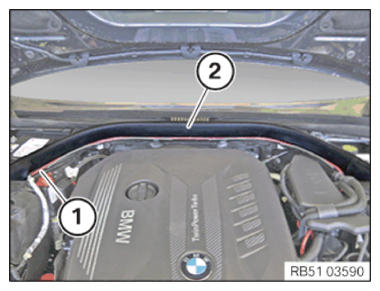
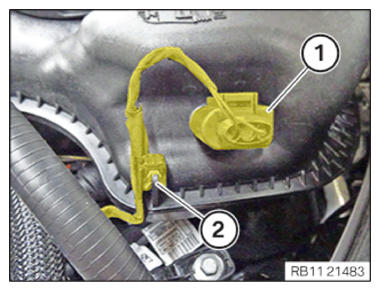
Push rear hood seal (2) into the guide.
Feed in cable (1) into the holders.
Check the seal for the rear hood (2) and the cable (1) for the correct fit.
- Version with a gasoline particulate filter:
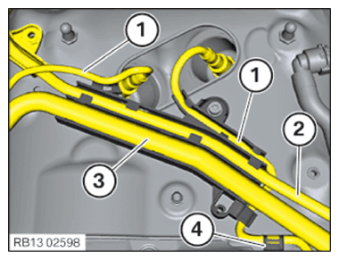
Clip the cable (1) of the lambda oxygen sensor into the holder.
Clip in the wiring harness (2).
Clip in the intake pipe (3).
Clip the cable of the Lambda oxygen sensor into the bracket (4).
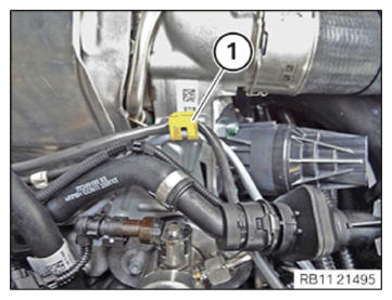
- Clip in the wiring harness mounting (1) at the heat shield.
- Feed the connector (2) of the Lambda oxygen sensor through.
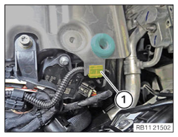
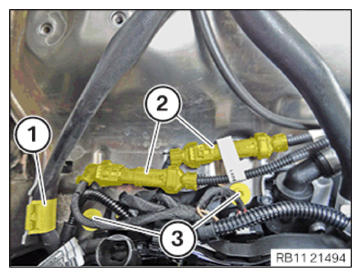
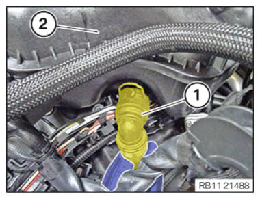
- Connect and lock the engine ventilation line to the retaining clip in the region of (1).
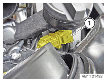
- Connect connectors (1) and lock.
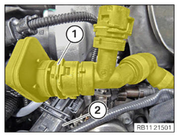
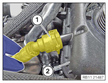
- Clip in the cable of the lambda oxygen sensor from the holder (1).
- Connect connectors (1) and lock.
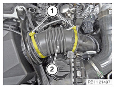
- Hose clamp
- Install bellows (2).
Tighten hose clamp (1).
TIGHTENING TORQUE SPECIFICATIONHose clamp Hose clamp Tightening torque 3 Nm - Clip in the cable from the Lambda oxygen sensor on the holder (1).
- Connect connectors (1) and lock.
- Install the lid (1) of the washer fluid reservoir downwards.
- Remove the side panel seal.
- Install clips (2).
- Install the expanding rivets (1).
- Feed the connector (2) of the Lambda oxygen sensor through.
- Connect and lock the engine ventilation line to the retaining clip in the region of (1).
- Connect connectors (1) and lock.
- Clip in the cable from the Lambda oxygen sensor on the holder (1).
- Clip in the wiring harness mounting (1) at the heat shield.
- Feed the connector (2) of the Lambda oxygen sensor through.
- Connect and lock the engine ventilation line to the retaining clip in the region of (1).
- Connect connectors (1) and lock.
- Clip in the cable from the Lambda oxygen sensor on the holder (1).
- Connect connectors (1) and lock.
- Install bellows (2).
- Tighten hose clamp (1).TIGHTENING TORQUES SPECIFICATION
Hose clamp Hose clamp Tightening torque 3 Nm - Connect and lock the engine ventilation line to the retaining clip in the region of (1).
- Clip in the cable from the Lambda oxygen sensor on the holder (1).
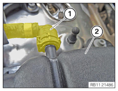
- Clip the connector (2) downwards into the heat shield.
- Clip the transmission wiring harness on to the bracket (1).
- Tighten down screws (1).TIGHTENING TORQUES SPECIFICATION
Support bridge M6x16 screw Tightening torque 10 Nm - Clip in the wiring harness from the attachment points (2).
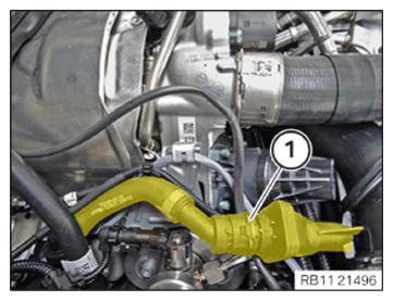
- Working downwards, clip in the engine ventilation line (1).
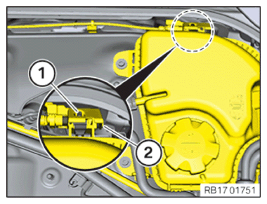
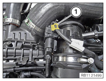
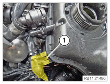
- Connect the wiring harness mounting to the snap-in lug (1) and lock it.
- Tighten down screws (1).TIGHTENING TORQUES SPECIFICATION
Coolant reservoir M6x20 screw Tightening torque 11 Nm - Clip in the coolant line to the bracket in the region (2).
- Connect the coolant line (1) to the coolant expansion tank (2) and lock it.
- Connect the coolant line (1) to the coolant expansion tank (2) and lock it.
- Connect the coolant line (1) to the coolant expansion tank (2) and lock it.
- Use clamping pliers to remove the coolant hoses (1) from the coolant expansion tank (2).
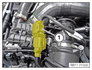
- Connect connectors (1) and lock.
- Clip the wiring harness into the wiring harness mounting (2).
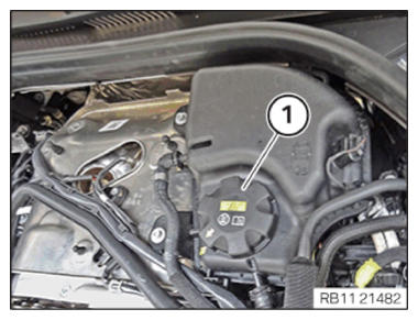
- Close the sealing cap (1) of the coolant expansion tank.
Follow-up work:
- Refer to INSTALLING THE CONTROL UNIT BRACKET FOR CYLINDERS 5 TO 8 (2018-2019) or INSTALLING THE CONTROL UNIT BRACKET FOR CYLINDERS 5 TO 8 (2020-2022) .
- Refer to INSTALLING THE COVER OF THE LEFT DME CONTROL UNIT .
- Refer to INSTALLING THE ACOUSTIC COVER (2018-2019) or INSTALLING THE ACOUSTIC COVER (2020-2022) .
- Refer to INSTALLING THE REAR RIGHT ENGINE COMPARTMENT COVER .
- Refer to INSTALLING THE COVER OF THE ENGINE COMPARTMENT ON THE REAR LEFT .
- Refer to INSTALLING THE COVER IN THE ENGINE COMPARTMENT ON TOP .
- Refer to INSTALLING THE COVER IN THE ENGINE COMPARTMENT ON THE TOP RIGHT .
- Refer to TAKING HOOD OUT OF THE SERVICE POSITION .
- Refer to FILLING AND VENTING THE HIGH-TEMPERATURE COOLANT CIRCUIT .
- Refer to CONNECTING ALL BATTERY GROUND LEADS .