Installing all pistons with connecting rod
NOTE:
The description is for one component only. The procedure is identical for all further components.
- Installing piston with connecting rod
NOTE:
RISK OF DAMAGE
Damage on the cylinder wall and oil spray nozzles.
A large force can scratch the cylinder wall and bend the oil spray nozzles.
Damage on the cylinder wall and oil spray nozzles.
A large force can scratch the cylinder wall and bend the oil spray nozzles.
- Carefully shift the piston and connecting rod in the engine block.
- Aligning piston rings
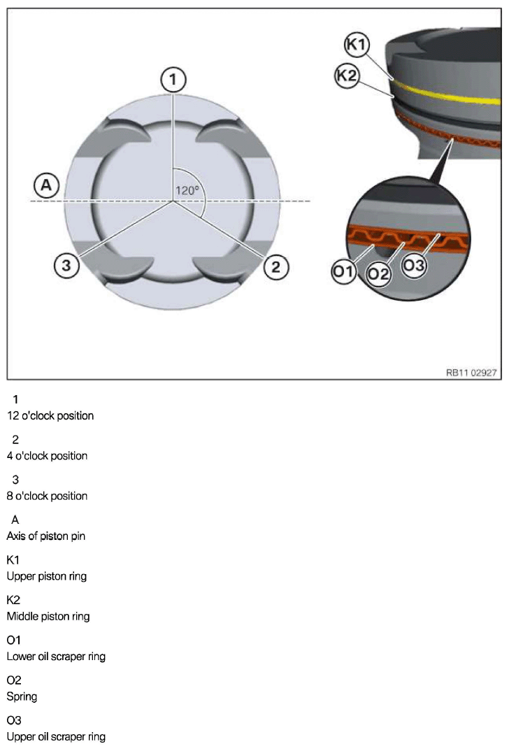
Aligning piston rings
- Align the contact points of all piston rings twisted by 120° each.
The piston ring gaps must not be positioned in line with the axis of the piston pin (A).
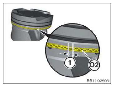
Piston ring Alignment Lower oil scraper ring (03) 12 o'clock position (1) Spring (02) 4 o'clock position (2) Upper oil scraper ring (01) 8 o'clock position (3) Central piston ring (K2) 12 o'clock position (1) Upper piston ring (K1) 4 o'clock position (2) - Make sure that the spring (02) does not overlap the piston ring gap (1).
- Coat the pistons (1) and piston rings lightly with oil.
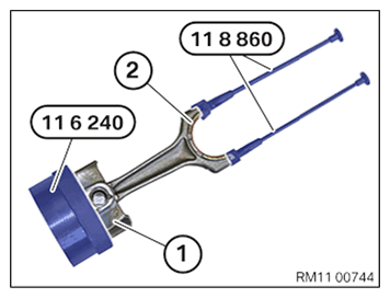
- Insert the pistons (1) with the piston rings into the connector 0 495 373 (11 6 240).
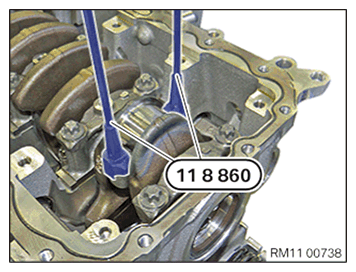
- Screw special tool 0 496 144 (11 8 860) on at large connecting rod eye (2).
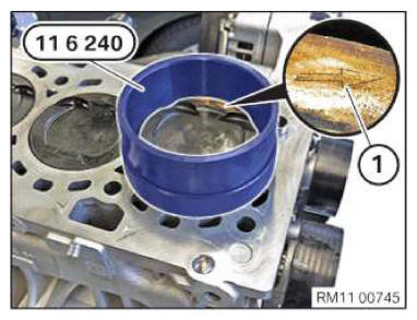
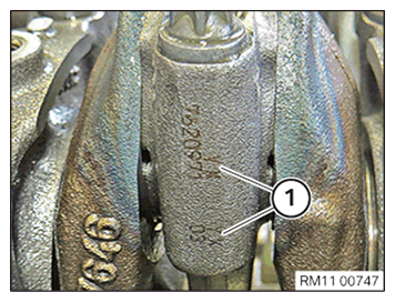
- Align the piston so that the arrow (1) points to cylinder 1.
- Insert the piston with the connecting rod into the special tool 0 495 373 (11 6 240) and guide it into the cylinder.
NOTE:
RISK OF DAMAGE
Damage on the cylinder wall and oil spray nozzles.
A large force can scratch the cylinder wall and bend the oil spray nozzles.
Damage on the cylinder wall and oil spray nozzles.
A large force can scratch the cylinder wall and bend the oil spray nozzles.
- Carefully shift the piston and connecting rod in the engine block.
- Push in piston by hand with only little force. Do not use striking tools.
- Install the lower connecting rod bearing
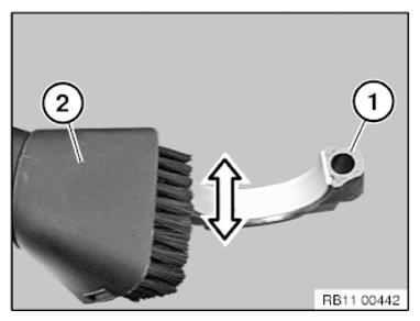
- Vacuum the connecting rod bearing shell and cracked surface (1) with a vacuum cleaner (2).
- Insert the connecting rod bearing shell (1) into the connecting rod bearing cap (2).
- Apply a light coat of oil to the connecting rod bearing shell (1).
- If necessary screw the inlet guide 0 496 144 (11 8 860) into the large connecting rod eye.
- Pull the connecting rod up to the connecting rod bearing journal.
NOTE:
RISK OF DAMAGE
Engine damage caused by incorrectly installed bearing shells and bearing brackets.
If the bearing shells and bearing brackets are installed incorrectly, then engine damage can occur.
Engine damage caused by incorrectly installed bearing shells and bearing brackets.
If the bearing shells and bearing brackets are installed incorrectly, then engine damage can occur.
- Always install all bearing shells and bearing brackets in the same position from which they were removed.
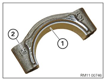
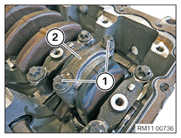
- Attach the connecting rod bearing caps to the connecting rod until the designations (1) match.
Make sure that the connecting rod bearing (2) is attached to the same connecting rod that it was detached from.
- A mixed installation of the connecting rod bolts (A) and (B) on a connecting rod bearing cap is not permissible.
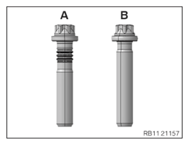
NOTE:
TECHNICAL INFORMATION
When installing new connecting rod bolts, you must ensure that two connecting rod bolts are always used on one connecting rod bearing cap.
Mixed installation of various connecting rod bolts on one connecting rod bearing cap is not permitted.
When installing new connecting rod bolts, you must ensure that two connecting rod bolts are always used on one connecting rod bearing cap.
Mixed installation of various connecting rod bolts on one connecting rod bearing cap is not permitted.
- Replace screws (1).
- Tighten the screws.
Make sure that the connecting rod bearing cap (2) rests completely on the connecting rod.
TIGHTENING TORQUES SPECIFICATIONConnecting rod bearing cap to connecting rod Replace screws.
Tighten screws crosswise.Joining torque 20 Nm 1. Angle of rotation 70° 2. Angle of rotation 70°
Follow-up work
- Refer to INSTALLING THE OIL DEFLECTOR
- Refer to PREPARING THE OIL VACUUM PUMP .
- Refer to INSTALL THE OIL VACUUM PUMP .
- Refer to REFITTING ENGINE OIL PAN
- Refer to INSTALLING THE FLYWHEEL .
- Refer to INSTALLING STARTER MOTOR .
- Refer to INSTALLING THE ACOUSTIC COVER FOR THE OIL SUMP .
- Refer to BLOCK THE CRANKSHAFT IN HE TDC FIRING POSITION OF CYLINDER 1
- Refer to SEAL THE OIL DUCT .
- Refer to CLEAN SEALING SURFACES .
- Refer to REPLACE CYLINDER HEAD GASKET .
- Refer to INSTALLING THE CYLINDER HEAD .
- Refer to ADJUSTING THE CAMSHAFTS WITH THE SPECIAL TOOL .
- Refer to INSTALL EXHAUST CAMSHAFT ADJUSTER .
- Refer to INSTALLING THE INTAKE ADJUSTER .
- Refer to INSTALLING THE VANOS CENTRAL VALVE OF THE INTAKE ADJUSTER .
- Refer to INSTALLING THE VANOS CENTRAL VALVE OF THE EXHAUST CAMSHAFT ADJUSTER .
- Refer to PRE-TENSIONING THE TIMING CHAIN WITH THE SPECIAL TOOL .
- Refer to TIGHTENING THE VANOS CENTRAL VALVE OF THE EXHAUST CAMSHAFT ADJUSTER .
- Refer to TIGHTENING THE VANOS CENTRAL VALVE OF THE INTAKE ADJUSTER .
- Refer to DISASSEMBLING ALL SPECIAL TOOLS
- Refer to INSTALL CHAIN TENSIONER .
- Refer to CHECKING THE TIMINGS OF THE CAMSHAFT
- Refer to INSTALLING THE HOLDER FOR THE THERMOSTAT ON THE TRANSMISSION OIL LINES .
- Refer to INSTALLING THE THERMOSTAT ON THE TRANSMISSION OIL LINES .
- Refer to INSTALLING THE OIL RETURN LINE FOR THE EXHAUST TURBOCHARGER .
- Refer to INSTALL THE COOLANT RETURN LINE FOR THE EXHAUST TURBOCHARGER .
- Refer to INSTALLING COOLANT FEED LINE FOR EXHAUST TURBOCHARGER .
- Refer to INSTALLING CYLINDER HEAD COVER .
- Refer to INSTALLING BOTH ACTUATORS .
- Refer to INSTALLING THE HEAT SHIELD ON THE CYLINDER HEAD
- Refer to PREPARE THE INJECTORS FOR INSTALLATION .
- Refer to INSTALLING THE RAIL WITH INJECTORS .
- Refer to INSTALLING HIGH PRESSURE PUMP .
- Refer to INSTALLING THE HIGH-PRESSURE LINE BETWEEN THE HIGH-PRESSURE PUMP AND THE HIGH-PRESSURE RAIL .
- Refer to INSTALLING ALL SPARK PLUGS .
- Refer to TOPPING UP THE MOTOR OIL .
- Refer to REMOVING THE ENGINE FROM ASSEMBLY JIG
- Refer to INSTALL ENGINE .