Installing torsion springs (540i 2017-2022, 540i xDrive 2017-2022)
Further information is available.
Injury hazard!
- The use of the specified special tool (tool) is mandatory.
- Carry out the described steps properly.
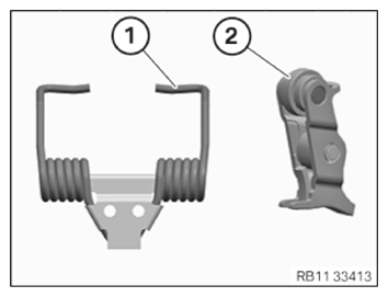
- Version with a torsion spring with an L-shaped contour and a suitable intermediate lever:
Use torsion spring (1) with an L-shaped contour only in conjunction with a suitable intermediate lever (2).
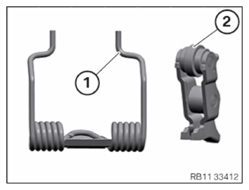
- Version with a torsion spring with an S-shaped contour and a suitable intermediate lever:
Use torsion spring (1) with an S-shaped contour only in conjunction with a suitable intermediate lever (2).
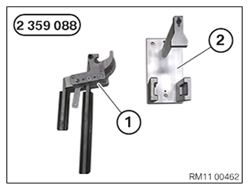
- Keep set of special tools 2 359 088 for removing the torsion spring with an S-shaped contour ready:
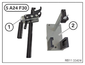
Number Description 1 Clamping lever 2 Mount for the clamping lever (torsion spring with an S-shaped contour) - Keep set of special tools 5 A24 F30 or, alternatively, the modified special tool 2 359 088 for removing the torsion spring with an L/S-shaped contour ready:
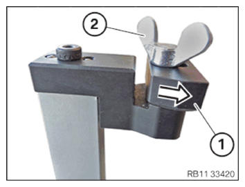
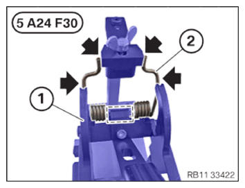
Number Description 1 Clamping lever 2 Mount for the clamping lever (torsion spring with an L/S-shaped contour) - Version with a torsion spring with an S-shaped contour with special tool 5 A24 F30 or the modified special tool 2 359 088:
Move shaped part (1) to the contact surface in the arrow direction.
Turn wing screw (2) until hand-tight.
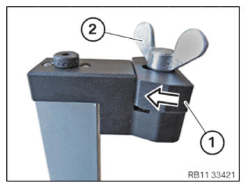
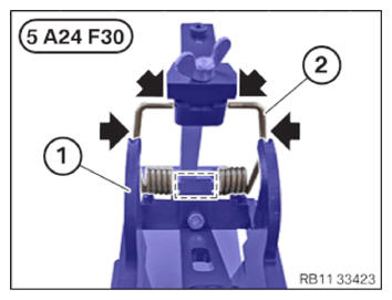
- Version with a torsion spring with an L-shaped contour with special tool 5 A24 F30 or the modified special tool 2 359 088:
Move shaped part (1) to the contact surface in the arrow direction.
Turn wing screw (2) until hand-tight.
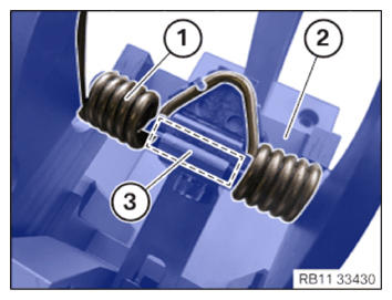
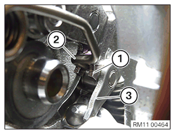
- Position torsion spring (1) in clamping lever (2).
Torsion spring (1) must be positioned correctly in the marked area (3) of clamping lever (2).
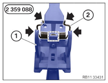
- Version with a torsion spring with an S-shaped contour with special tool 2 359 088:
Close clamping lever (1) of special tool 2 359 088 carefully in the corresponding mount until the snap-in hooks engage audibly.
Ensure that torsion spring (2) lies correctly in the lateral guides (arrows) and mark of clamping lever (1) when tensioning.
- Version with a torsion spring with an S-shaped contour with special tool 5 A24 F30 or the modified special tool 2 359 088:
Close clamping lever (1) of special tool 5 A24 F30 or the modified special tool 2 359 088 carefully in the corresponding mount until the snap-in hooks engage audibly.
Ensure that torsion spring (2) lies correctly in the lateral guides (arrows) and mark of clamping lever (1) when tensioning.
- Version with a torsion spring with an L-shaped contour with special tool 5 A24 F30 or the modified special tool 2 359 088:
- Close clamping lever (1) of special tool 5 A24 F30 or the modified special tool 2 359 088 carefully in the corresponding mount until the snap-in hooks engage audibly.
- Ensure that torsion spring (2) lies correctly in the lateral guides (arrows) and mark of clamping lever (1) when tensioning.
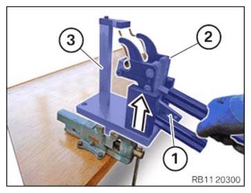
- Move clamping lever (2) with the tensioned torsion spring carefully out of mount (3) in the arrow direction.
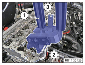
- Insert torsion spring (2) with clamping lever (1) into cylinder head (3).
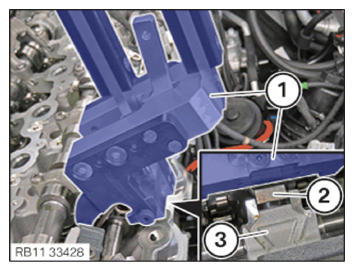
- Version with a torsion spring with an S-shaped contour on an intermediate lever
- Insert the torsion spring (2) into the intermediate levers (1).
- Check all roller cam followers (3) for correct installation position.
- Place clamping lever (1) flat in the marked area (2).
- Press together clamping lever (1) until snap-in hooks (3) unlock audibly.
- Open clamping lever (1) carefully until the torsion spring is fully relaxed.
- Guide out and remove clamping lever (1).
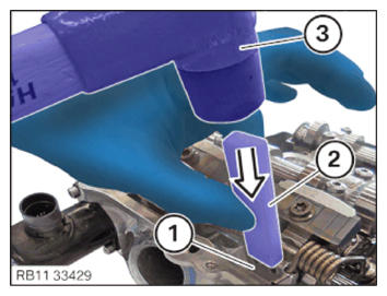
- Fit torsion spring (1) correctly in the arrow direction using a standard plastic hammer (3) and a standard plastic wedge (2).
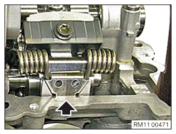
- Check the correct installation position of the torsion spring (arrow).