Overview - Oil Pan/Oil Pump
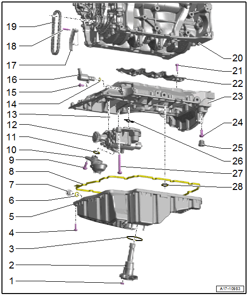
- Nut
- 9 Nm
- Oil Level Thermal Sensor -G266-
- Removing and Installing. Refer to Oil Level Thermal Sensor -G266-, REMOVING AND INSTALLING .
- Seal
- Replace after removing
- Bolt
- Replace after removing
- Tightening sequence. Refer to Fig 2.
- Oil Pan Lower Section
- Removing and Installing. Refer to OIL PAN LOWER SECTION, REMOVING AND INSTALLING .
- O-Ring
- Replace after removing
- coat with engine oil
- Plugs
- Turn until it stops
- Seal
- Replace after removing
- Bolt
- 4 Nm +45°
- Replace after removing
- Suction Line
- Clean the screen if there are debris
- O-Ring
- Replace after removing
- Coat with engine oil
- Oil Pump
- Removing and Installing. Refer to OIL PUMP, REMOVING AND INSTALLING .
- Centering Bracket
- For the oil pump
- Quantity: 2
- O-Ring
- Replace after removing
- Coat with engine oil
- Bolt
- -item : Bolt
- Oil Pressure Regulation Valve -N428-
- Chain Tensioner
- Guide Pin
- 9 Nm
- Oil Pump Drive Chain
- Mark the running direction before removal
- Cylinder Block
- Bolt
Aluminum bolt
- 4 Nm +90°
Steel bolt
- Self-locking
- 9 Nm
- Replace after removing
- 4 Nm +90°
- Oil Baffle
- Oil Pan Upper Section
- Removing and Installing. Refer to OIL PAN UPPER SECTION, REMOVING AND INSTALLING .
- Bolt
- Plug
- Quantity: 3
- Oil Screen
- Bolt
Aluminum bolt
- 8 Nm +90°
Steel bolt
- 16 Nm + 90°
- Replace after removing
- 8 Nm +90°
- O-Ring
- Replace after removing
- Coat with engine oil
Oil Pan Lower Section - Tightening Specifications and Sequence
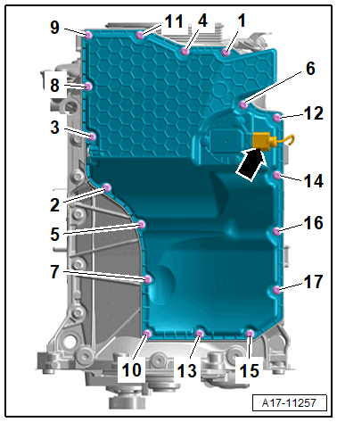
- Replace bolts that were tightened with an additional turn after removing them.
-- Tighten the bolts -1 to 17- in steps in the sequence shown:
| Step | Tightening Specification/Additional Turn |
|---|---|
| 1. | Install all the way by hand |
| 2. | 8 Nm |
| 3. | 90° additional turn |
Oil Pan Upper Section Bolts M8x20 - Versions
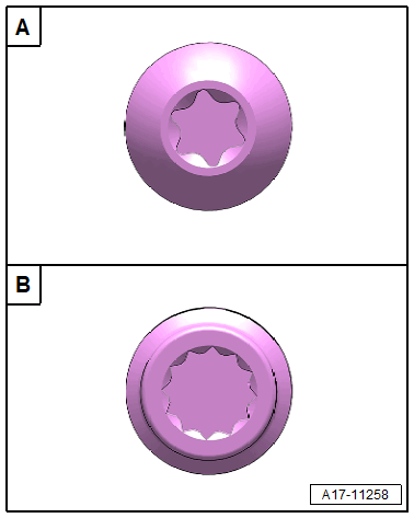
A - Version 1
- With Torx bolt head
B - Version 2
- With multi-point bolt head
Oil Pan Upper Section - Tightening Specifications and Sequence
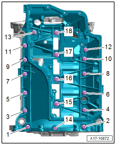
- Replace bolts that were tightened with an additional turn after removing them.
-- Tighten the version 1 bolts (refer to Fig 3) gradually in the sequence shown.
| Step | Bolts | Tightening Specification/Additional Turn |
|---|---|---|
| 1. | -1 through 18- | 8 Nm |
| 2. | -1 through 13- | 45° additional turn |
| 3. | -14 through 18- | 90° additional turn |
-- Tighten the version 2 bolts (refer to Fig 3) gradually in the sequence shown.
| Step | Bolts | Tightening Specification/Additional Turn |
|---|---|---|
| 1. | -1 through 13- | 15 Nm |
| 2. | -14 through 18- | 8 Nm |
| 3. | -1 through 18- | 90° additional turn |