Heater Core, Removing And Installing: Removing
-- Perform the preparation work for removing the heater core. Refer to HEATER CORE, PREPARING FOR REMOVAL .
-- Remove the plenum chamber cover. Refer to PLENUM CHAMBER COVER, REMOVING AND INSTALLING .
The cooling system is under pressure when the engine is warm. There is a risk of scalding from hot steam and coolant.
Scalding the skin and other parts of the body is possible.
- Wear safety gloves.
- Wear protective eyewear.
- Reduce the pressure by covering the coolant expansion tank cap with a cloth and carefully opening it.
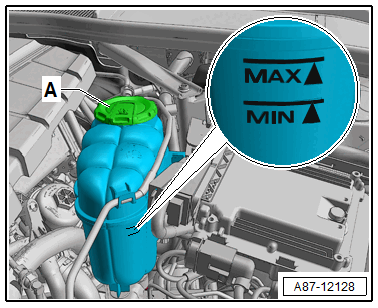
-- Carefully open the coolant expansion tank cap -A- (do not completely remove).
TIP
- There are different versions of the coolant expansion tank and in different layouts in the plenum chamber and in the engine compartment. Refer to COOLANT, DRAINING AND FILLING .
-- Mark the layout of the coolant hoses on the connections to the heat exchanger -A- (supply to the heat exchanger in the heater and A/C unit) and -B- (engine return).
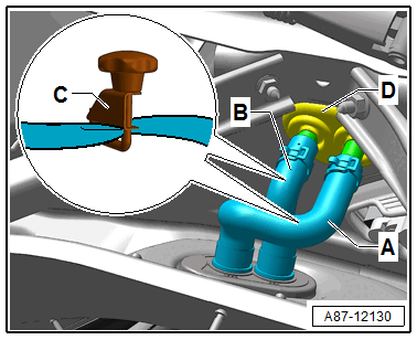
-- Clamp the coolant hoses -A- and -B- with hose clamps -C-.
-- Cover the area beneath connections for coolant hoses -A- and -B-, for example with absorbent paper.
-- Place a small container under the connections for coolant hoses -A- and -B- (to the heater core).
-- Remove the coolant hoses -A- and -B- from the connections to the heater and A/C unit heater core.
-- Insert one section each of hose -A- and -B- on to both connections to heater core.
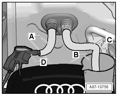
-- Place a container -B- under the other end of the hose -C-.
-- Using a compressed air gun -D-, carefully blow the coolant out of the heater core (against the normal flow direction of the coolant) using the hose -A- into a container -B-.
-- Cover the floor covering and the center tunnel under the left and right heater core -A- with waterproof foil and absorbent paper.
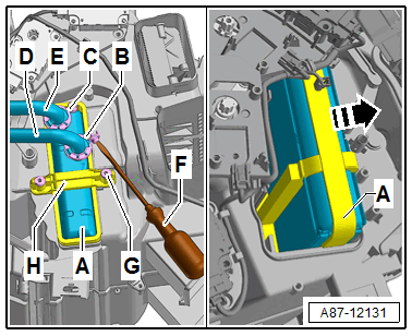
-- Remove the bolt from the screw-type clamp -B- and remove the screw-type clamp.
TIP
- The bolts in the screw-type clamps -B- and -C- can be removed with a longer T15 Torx wrench -F-. Depending on the version of the heater and A/C unit for certain market specific vehicles instead of the Torx bolt, 3 mm hex socket bolt can be installed.
- If the screw-type clamps -B- and/or -C- are located unfavorably so that the bolts are not accessible, these can be carefully turned if necessary (with slight force and a screwdriver).
- The bolt -G- and the bracket -H- remain removed (for example on a "Low" A/C system).
- If on a "High" A/C system due to the position of the screw-type clamps -B- and/or -C- it is necessary, remove the bracket -H- (otherwise the bracket remains installed). Refer to Rear Temperature Control Door Motor .
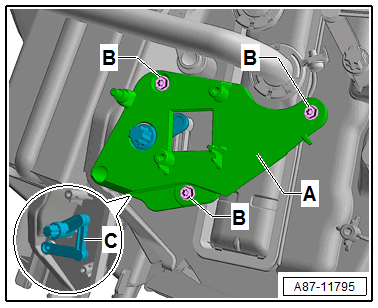
-- Remove the bolt from the screw-type clamp -C- and remove the screw-type clamp.
Vehicles with a "High" A/C system
-- Check the adjustment of the temperature control door for the right side -A- in the heater and A/C unit via the adjustment of the lever -B-, the lever -B- must be in the position shown.
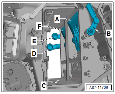
Continuation for All Vehicles
TIP
The left temperature control door -F- is already positioned in the correct position before switching off the ignition. Refer to HEATER CORE, PREPARING FOR REMOVAL .
Risk of damaging the temperature control doors in the heater and A/C unit when removing the heater core.
- Check via the lever -B- that the temperature control door -A- is in the "cold" position.
-- Push the heat exchanger in the direction of the "right footwell" so that both coolant pipes -D- and -E- can be loosened from the heat exchanger connections.
-- Remove the heat exchanger -A- in the direction of the -arrow- from the heater and A/C unit in the right footwell (front passenger side).
-- Remove the O-ring seals from the coolant pipes -D- and -E- (or from the heater core connections).