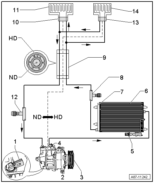
System Overview - Refrigerant Circuit With Expansion Valve And Receiver/Dryer
NOTE:
The arrows indicate the refrigerant flow direction.
The following illustration shows a refrigerant circuit with two evaporators and an internal heat exchanger as an example.
The layout of the refrigerant circuit is vehicle-specific. Refer to Refrigerant Circuit .
HD = High Pressure Side
ND = Low Pressure Side
- A/C Compressor Regulator Valve -N280-
- A/C Compressor
- Belt Pulley
- Depending on the version a A/C Clutch -N25- is installed in the belt pulley. Refer to Refrigerant Circuit .
- Depending on the version instead of the belt pulley a drive unit can also be present. Refer to Refrigerant Circuit .
- Pressure Relief Valve
- Refrigerant Pressure Sensor
- Vehicle-specific version. Refer to Refrigerant Circuit .
- Condenser (with Receiver/Dryer)
- Receiver/Dryer
- Installed on a condenser or in the condenser. Refer to Refrigerant Circuit .
- With dryer cartridge
- Service Connection - High Pressure Side
- With closure cap
- Refrigerant Line with Inner Heat Exchanger
- Front Expansion Valve
- Front Evaporator
- Evaporator in the front heater and A/C unit (installed under the instrument panel)
- Service Connection - Low Pressure Side
- With closure cap
- Rear Expansion Valve
- Only present in vehicles with a rear A/C unit (optional equipment)
- Rear Evaporator
- Only present in vehicles with a rear A/C unit (optional equipment)