Transmission Control Module -J217-, REMOVING AND INSTALLING: Installing
Install in the reverse order of removal while noting the following:
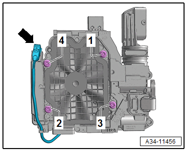
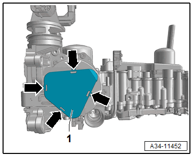
- Before installing the control module, clean the threaded holes of oil and debris.
-- Push the control module evenly on the valve body and tighten the bolts in the sequence -1 to 4- to the tightening specification.
Tip:
-- Push in the sensor arm -1- on the ATF pump -2- by hand and tighten the bolts -arrows- hand-tight.
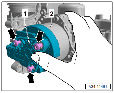
There is a risk of damaging the ATF pump.
- The sensor arm -1- must make contact when attaching the ATF pump -2-.
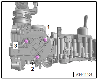
-- Tighten the bolts to the specification in the following sequence: -1 through 3-.
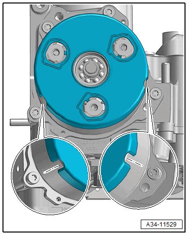
-- Install the cover -1- for the sensor arm -arrows-.
-- Install the Hydraulic Pressure Sensor 1 -G545- and Hydraulic Pressure Sensor 2 -G546-.
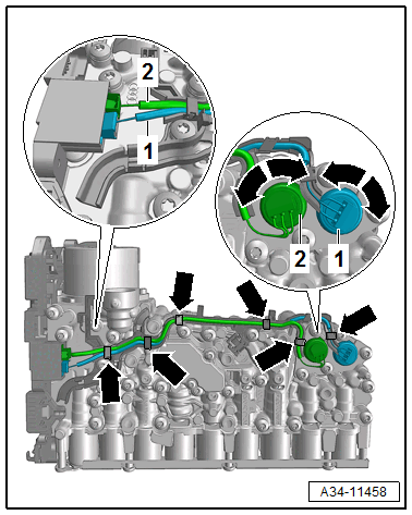
- Do not interchange the connectors.
- Make sure that the connection is correct as shown -1 and 2-. Refer to Hydraulic Pressure Sensor 1 -G545- AND Hydraulic Pressure Sensor 2 -G546-, REMOVING AND INSTALLING .
-- Install the Mechatronic. Refer to MECHATRONIC, REMOVING AND INSTALLING .
- If the Transmission Control Module -J217- was replaced, the function "control module replacing" must be performed using the Vehicle Diagnostic Tester.
- If the valve body is replaced, the "valve body, replacing" function must be performed using the Vehicle Diagnostic Tester.
-- Connect the Vehicle Diagnostic Tester with the vehicle.
- Network plan or control module list
- 02 - Transmission Electronics, Guided Functions
- 02 - Control Modules/Mechatronic, Replacing
- or
- 02 - Valve Body, Replacing
-- Start the selected program and follow the instructions in the display of the Vehicle Diagnostic Tester.