Input Shaft 1, Disassembling And Assembling: Assembling
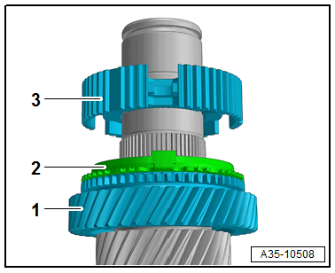
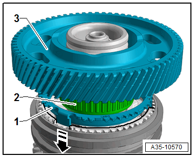
-- Install the 5th gear wheel -1- with the synchronizer ring -2- and position the synchronizer hub -3- with the lettering facing upward.
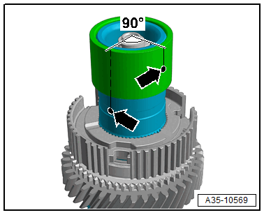
-- Install the bearing inner race while positioning the fluid holes -arrows- at an approximately 90° offset.
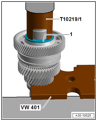
-- Using the Wishbone Rubber Mount Assembly Tool :T10219 , press the bearing inner race -1- with the synchronizer hub -2- up to approximately two-thirds of the way on before the stop.
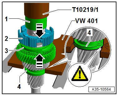
- Installation position: the lettering on the bearing -1- (thicker wall thickness) points to the Wishbone Rubber Mount Assembly Too :T10219 .
-- Lift the 5th gear synchronizer ring with the 5th gear wheel -3- until the synchronizer ring anti-twist mechanism joins with the synchronizer hub cut-out -arrows-.
-- At the same time, install the bearing inner race -1- and synchronizer hub -2- until they stop.
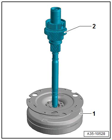
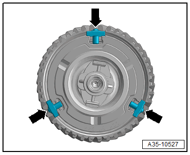
-- Use the flywheel -1- as an assembly stand for input shaft 1 -2- as shown.
-- Insert the three thrust pieces -arrows-.
-- Push the double-toothed locking collar onto the opening -arrow A- with the lettering facing upward.
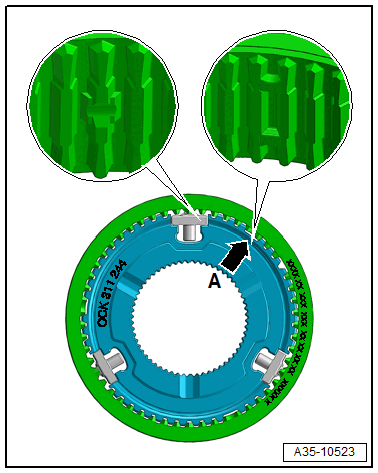
-- Press the tops of the thrust pieces in slightly by hand when installing.
-- Mount the synchronizer ring -1- with the 7th gear needle bearing -2- and 7th gear wheel -3-.
Tip:
- Deposits and debris on the thrust washer -1- are not critical.
- Clean the thrust washer before installing if necessary.
-- Install the thrust washer -1- using the Wishbone Rubber Mount Assembly Tool :T10219 .
If removed, press on the sensor wheel.
Press on the sensor wheel 6
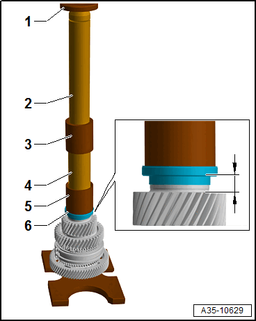
- Installation position: the high collar points to the Extracting Tool - Thrust Piece :T40413/11 -5-.
- The dimension on the input shaft 1 is specified by the Extracting Tool - Thrust Piece :T40413/11
1 - Press Piece - Multiple Use :VW412
2 - Drive Sleeve :30-20
3 - Press Piece - Trailing Arm :2010
4 - Press Piece - Front Control Arm :2040
5 - Extracting Tool - Press In Piece :T40413/11
-- Press on the sensor wheel -6- all the way.