Inner Output Shaft, Disassembling And Assembling, Only Vehicles With Self-Locking Center Differential
Special tools and workshop equipment required
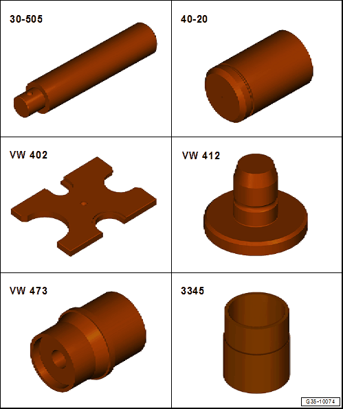
- Locking Pin Driver :30-505
- Bearing Installer - Multiple Use :40-20
- Press Plate :VW402
- Press Piece - Multiple Use :VW412
- Press Piece - Multiple Use :VW473
- Bearing Installer - Wheel Bearing :3345
Special tools and workshop equipment required
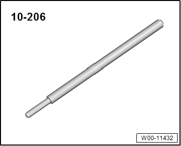
- Valve Guide/Clutch Release Push Rod Seal Drift :10-206
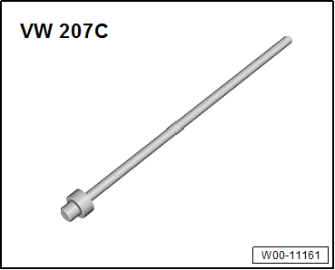
- Piston Pin Drift :VW207
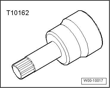
- Socket - Xzn 18mm :T10162A
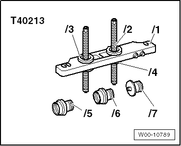
- Gearbox Assembly Tool :T40213A
- Extracting Tool - Adapter :T40413/7
- Extracting Tool - Pin :T40413/9
- Inner output shaft, removing. Refer to Inner Output Shaft Roller Bearing, Removing, Vehicles with Self-Locking Center Differential .
Disassembling
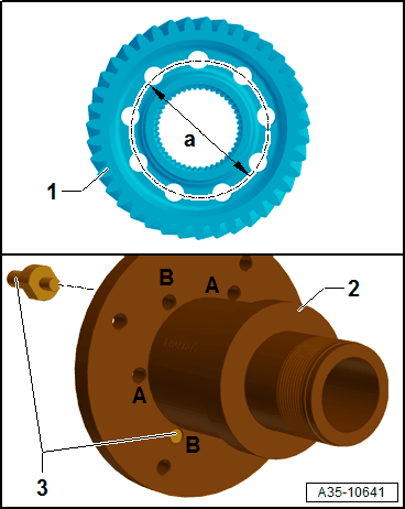
-- Depending on the diameter -a- install the three Extracting Tool - Pin :T40413/9 -3- in the Extracting Tool - Adapter :T40413/7 -2- in the hole in the gear for the inner output shaft -1-.
- Dimension -a- = 62 mm (2.44 in.) threaded holes -A-
- Dimension -a- = 64 mm (2.52 in.) threaded holes -B-
-- Bolt the Extracting Tool - Adapter :T40413/7 with the Gearbox Assembly Tool :T40213A .
-- Tighten the Gearbox Assembly Tool :T40213A in the vise or on the Gearbox Support :T40206 .
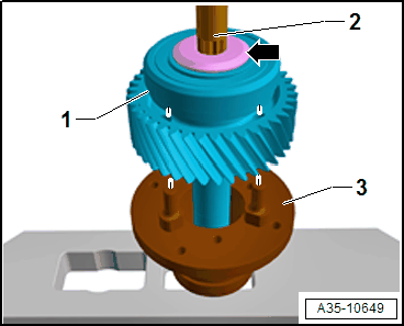
-- Position the inner output shaft -1- on the Extracting Tool - Adapter :T40413/7 -3-.
-- Warm the bolt -arrow- to approximately 100 °C (212 °F).
-- Remove the bolt -arrow- with the Socket - Xzn 18mm :T10162A -2- from the inner output shaft -1-.
Tip:
- The bolt from the output shaft has a very high loosening torque.
If when warning the bolt the oil pipe -3- in the inner output shaft is damaged it must be replaced.
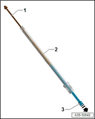
-- Drive out the oil pipe -3- using the Valve Guide/Clutch Release Push Rod Seal Drift :10-206 -2- and Piston Pin Drift :VW207 -1- in -direction of the arrow- out of the inner output shaft.
-- Drive in the new oil pipe on the opposite side again.
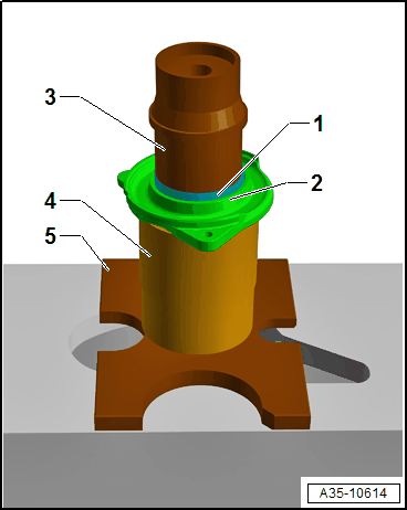
Inner output shaft 1, pressing out
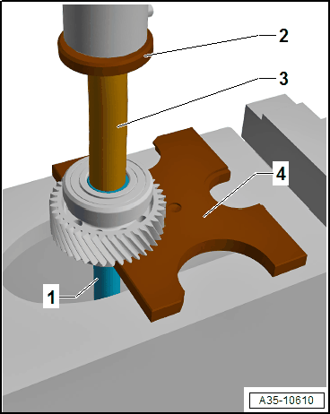
2 - Press Piece - Multiple Use :VW412
3 - Locking Pin Driver :30-505
4 - Press Plate :VW402
- All additional components remaining on the Press Plate :VW402 must be secured from falling.
-- When removing the components in the sequence, at the same time pay attention to the installation position. Refer to OVERVIEW - OUTPUT SHAFT, VEHICLES WITH SELF-LOCKING CENTER DIFFERENTIAL .
Roller bearing 1 from the bearing shell 2, pressing out
3 - Press Piece - Multiple Use :VW473
4 - Bearing Installer - Wheel Bearing :3345
5 - Press Plate :VW402
- Remove the locking ring -Item 4- beforehand.
Assembling
Drive wheel for spur gear unit 1, pressing on
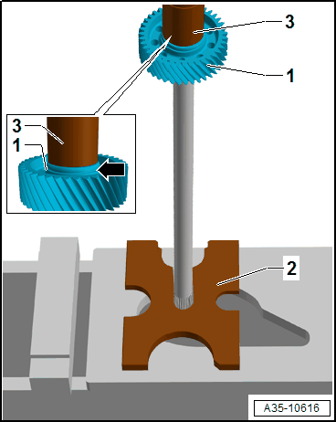
2 - Press Plate :VW402
3 - Bearing Installer - Multiple Use :40-20
- Installation position: the groove -arrow- from the drive wheel for spur gear unit -1- points to the Bearing Installer - Multiple Use :40-20 .
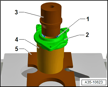
Ball bearing 1, pressing on
3 - Press Plate :VW402
4 - Bearing Installer - Multiple Use :40-20
- Installation position: the shoulder -arrow- points to the drive wheel for spur gear unit -2-.
-- Depending on the diameter -a- install the three Extracting Tool - Pin :T40413/9 -3- in the Extracting Tool - Adapter :T40413/7 -2- in the hole in the gear for the inner output shaft -1-.
- Dimension -a- = 62 mm (2.44 in.) threaded holes -A-
- Dimension -a- = 64 mm (2.52 in.) threaded holes -B-
-- Bolt the Extracting Tool - Adapter :T40413/7 with the Gearbox Assembly Tool :T40213A .
-- Tighten the Gearbox Assembly Tool :T40213A in the vise or on the Gearbox Support :T40206 .
-- Position the inner output shaft -1- on the Extracting Tool - Adapter :T40413/7 -3-.
-- Clean the internal threads of the inner output shaft with a thread tap.
-- Install the new bolt -arrow- using the Socket - Xzn 18mm :T10162A -2- and tighten.
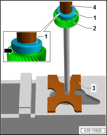
Roller bearing 1 in the bearing shell 2, pressing in
3 - Press Piece - Multiple Use :VW473
4 - Bearing Installer - Wheel Bearing :3345
5 - Press Plate :VW402
- Position the roller bearing -1- with the lettered side (larger panel thickness) to the Press Piece - Multiple Use :VW473 -3-.
-- Install the circlip -Item 4-.
Tightening Specifications