Input Shaft 2, Disassembling And Assembling
Special tools and workshop equipment required
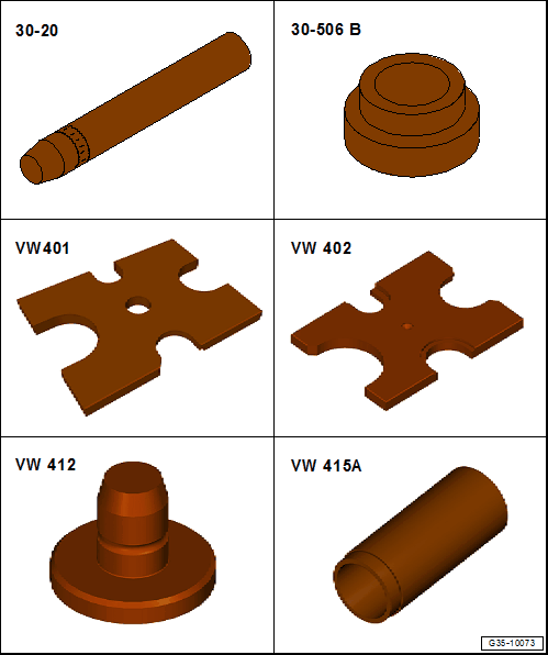
- Drive Sleeve :30-20
- Bearing Installer - Needle Bearing :30-506B
- Press Plate :VW401
- Press Plate :VW402
- Press Piece - Multiple Use :VW412
- Press Piece - 60mm :VW415A
Special tools and workshop equipment required
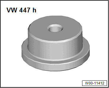
- Press Piece - Multiple Use :VW447H
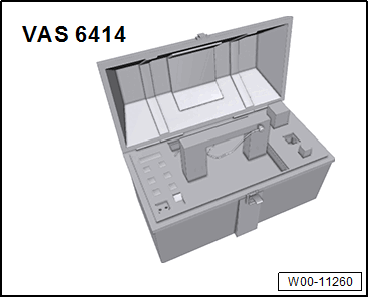
- Inductive Heater :VAS 6414
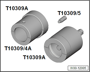
- Puller - Transmission Gears :T10309A
- Extracting Tool - Press In Piece :T40413/12
- Input shaft 2 removed. Refer to GEAR SET, DISASSEMBLING AND ASSEMBLING .
Disassembling
Pull off the sensor wheel 1 for the input shaft 2.
Tip:
- The Puller - Transmission Gears - Half Shell :T10309/3 -2- cannot be completely closed.
2 - Puller - Transmission Gears - Half Shell :T10309/3
3 - Puller - Transmission Gears :T10309/1
4 - Press Piece - Multiple Use :VW447H
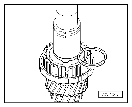
-- Remove the circlip -2-.

-- Remove the thrust washer -1- and 4th gear assembly -3- with the needle bearing.
Input shaft 2 1, pressing on
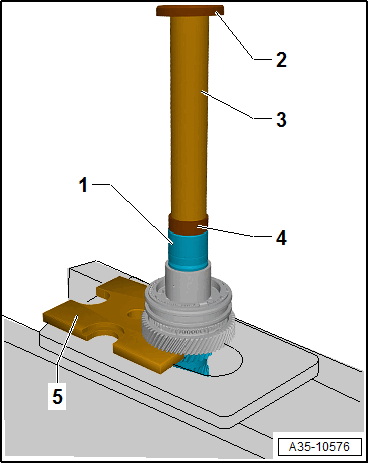
2 - Press Piece - Multiple Use :VW412
3 - Drive Sleeve :30-20
4 - Bearing Installer - Needle Bearing :30-506B
5 - Press Plate :VW401
- All additional components remaining on the Press Plate :VW401 must be secured from falling.
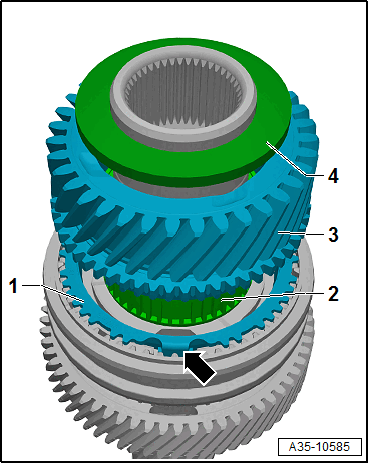
-- When removing the components in the sequence, at the same time pay attention to the installation position. Refer to OVERVIEW - INPUT SHAFT 2 .
Assembling
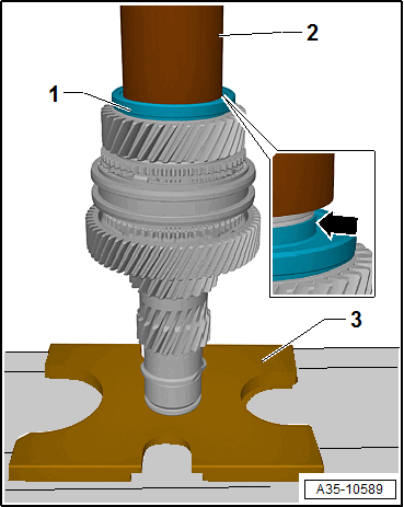
6th gear wheel inner race 1, installing
3 - Press Piece - 60mm :VW415A
4 - Press Piece - Multiple Use :VW412
- Beforehand, push on the thrust washer -2-.
- Warm the inner race -1- using the Inductive Heater :VAS 6414 to 100 °C (212 °F).
- Layout of the oil filler hole -arrows- at an offset of approximately 90°.
- Installation position: the lettering on the bearing -1- (thicker wall thickness) points to the Press Piece - 60mm :VW415A .
-- Press on the needle bearing for the 6th gear assembly -1-, 6th gear assembly -2- and synchronizer ring for 6th gear assembly -3-.
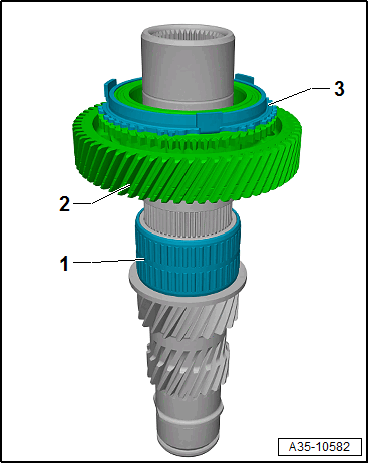
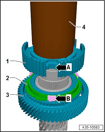
Synchronizer hub 1, pressing on
4 - Press Piece - 60mm :VW415A
-- Lift the 6th synchronizer ring -2- with 6th gear assembly -3- slightly, until the anti-twist mechanism -arrow B- of the synchronization is flush with the cut-outs -arrow A- of the synchronizer hub -1-.
- Warm the synchronizer hub -1- using the Inductive Heater :VAS 6414 to 100 °C (212 °F).
- The lettered side of the synchronizer hub points to the Press Piece - 60mm :VW415A .
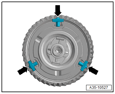
-- Insert the three thrust pieces -arrows-.
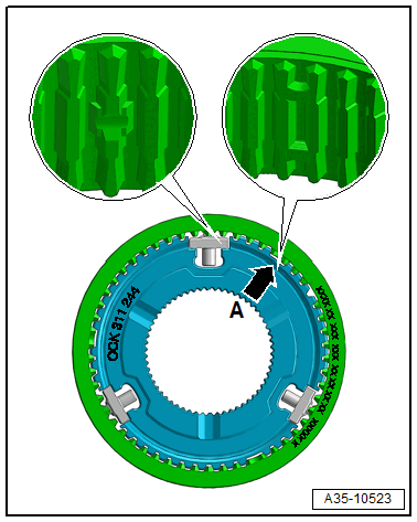
-- Push the double-toothed locking collar onto the opening -arrow A- with the lettering facing upward.
-- Press the tops of the thrust pieces in slightly by hand when installing.
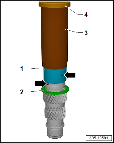
Inner race for 4th gear selector gear 1, pressing on.
2 - Press Piece - 60mm :VW415A
3 - Press Piece - Multiple Use :VW412
- Warm the inner race -1- using the Inductive Heater :VAS 6414 to 100 °C (212 °F).
- Layout of the oil filler hole -arrows- at an offset of approximately 90°.
- Installation position: the lettering on the bearing -1- (thicker wall thickness) points to the Press Piece - 60mm :VW415A .
-- Pressing on the 4th gear synchronizer ring -1-, needle bearing for 4th gear assembly -2-, 4th gear assembly -3- and 4th gear thrust washer -4-.
- The anti-twist mechanisms -arrow- of the synchronizer ring -1- must be flush with the cut-outs of the locking collar.
Determine the circlip for the 4th gear assembly
Tip:
- The illustration shows a different component. However, determining the circlip is identical.
-- Determine the thickest (but still usable) circlip and insert it. For the part number, refer to the => Parts Information.
The following circlips are available:
| Circlip thickness (mm) | ||
|---|---|---|
| 2.24 | 2.28 | 2.32 |
| 2.36 | 2.40 | 2.44 |
| 2.48 | 2.52 | |
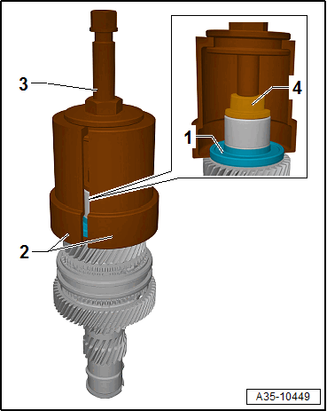
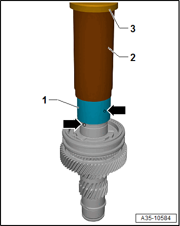
Press on the sensor wheel 1.
2 - Extracting Tool - Press In Piece :T40413/12
3 - Press Plate :VW402
- Installation position: the high collar -arrow- of the sensor wheel points to the Press Piece - 60mm :VW415A .
-- Press on the sensor wheel -1- all the way.