Engine, Removing, AUDI A4/A5
Special tools and workshop equipment required
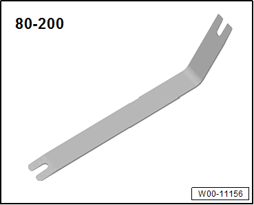
- Pry Lever: 80-200
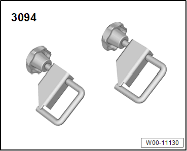
- Hose Clamps - Up To 25mm: 3094
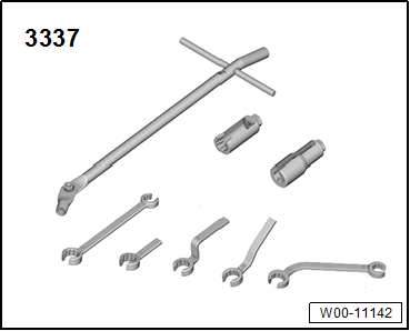
- Ring Wrench 7-Piece Set: 3337
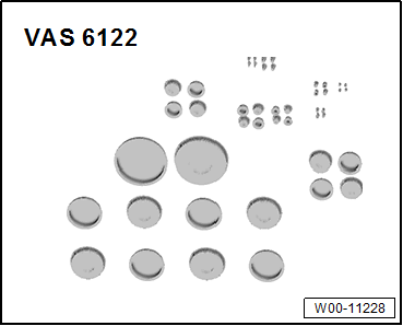
- Engine Bung Set: VAS6122
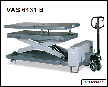
- Scissor Lift Table: VAS6131B
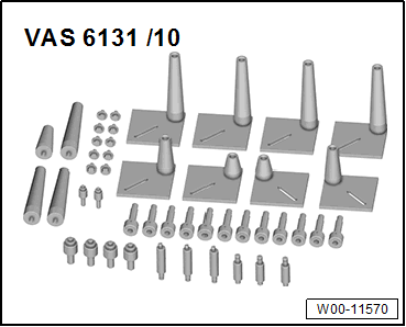
- Scissor Lift Table - Audi Set: VAS6131/10
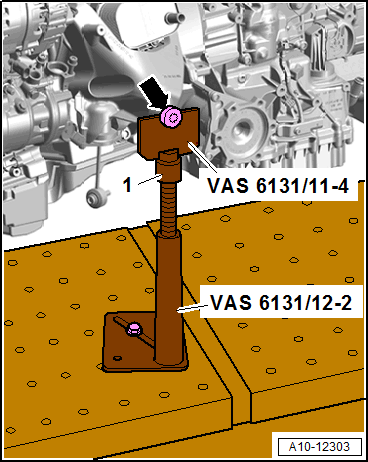
- (Quantity: 2) Scissor Lift Table - A8 Set - Mounting: VAS6131/11-4 from Scissor Lift Table - A8 Set: VAS6131/11 , not illustrated
- (Quantity: 2) Scissor Lift Table - A6 Set - Mounting Pins: VAS6131/12-2 from Scissor Lift Table - A6 Set: VAS6131/12 , not illustrated
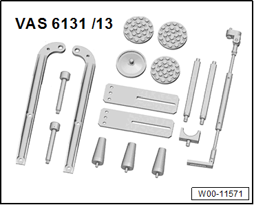
- (Quantity: 2) Threaded spindle from the Scissor Lift Table - Q7 Set: VAS6131/13
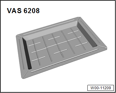
- Shop Crane - Drip Tray: VAS6208
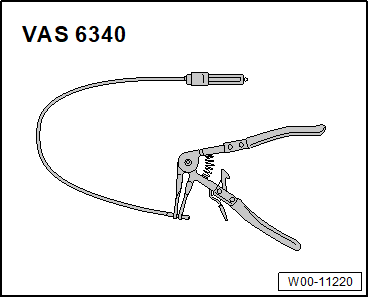
- Hose Clip Pliers: VAS6340
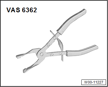
- Hose Clip Pliers: VAS6362
- Protective Eyewear
- Safety Gloves
Procedure
- With the lock carrier installed, the engine is removed downward with the transmission.
- During installation, all cable ties must be installed at the same location.
- During installation, all heat shield boots must be installed at the same location.
- Follow the guidelines for clean working conditions. Refer to GUIDELINES FOR CLEAN WORKING CONDITIONS .
- All bolts on suspension components with bonded rubber bushings must be tightened in curb weight position (no load).
- Bonded rubber bushings have a limited range of rotation. Axle components with bonded rubber bushings must be brought into the position they will be in when driving before they are tightened (curb weight position). Otherwise, the bonded rubber bushing will be under stress, which will reduce the service life.
-- Before starting the procedure, determine the curb weight position. Refer to WHEEL BEARING, LIFTING TO CURB WEIGHT POSITION, VEHICLES WITH COIL SPRING .
- AWD vehicles: the electro-mechanical parking brake must be released before disconnecting battery so the driveshaft can be rotated to remove it.
-- Move the front wheels so that they are in a straight-ahead position.
-- Disconnect the battery. Refer to BATTERY, DISCONNECTING AND CONNECTING .
The cooling system is under pressure when the engine is warm. There is a risk of scalding due to hot steam and hot coolant.
Scalding the skin and other parts of the body is possible.
- Wear safety gloves.
- Wear protective eyewear.
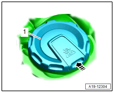
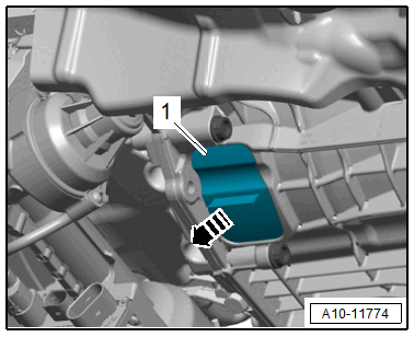
- Reduce the pressure by covering the coolant expansion tank cap with a cloth and carefully opening it.
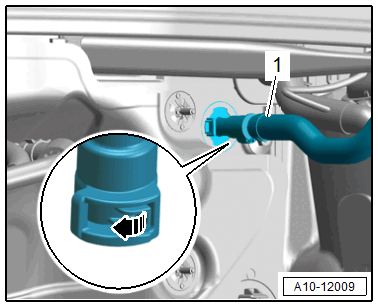
-- Open the cover -1- for the coolant expansion tank by releasing the catch in direction of -arrow-.
-- Remove the lock carrier cover. Refer to OVERVIEW - BUMPER COVER .
-- Remove the front wheels. Refer to the appropriate Service Information .
-- Remove the left and right wheel spoiler and loosen the right front wheel housing liners. Refer to OVERVIEW - FRONT WHEEL HOUSING LINER .
-- Loosen the left front wheel housing liner in the front area and push slightly toward the rear. Refer to OVERVIEW - FRONT WHEEL HOUSING LINER .
-- Remove the noise insulations. Refer to OVERVIEW - NOISE INSULATION .
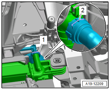
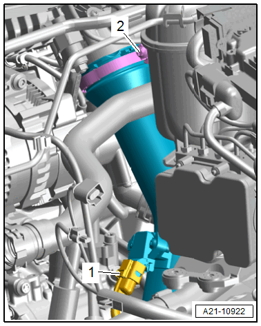
-- Disconnect the connector -2- for the Engine Coolant Temperature Sensor on Radiator Outlet -G83-.
-- Place the Shop Crane - Drip Tray: VAS6208 underneath.
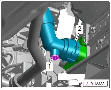
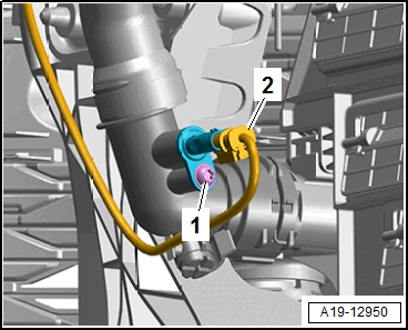
-- Lift the clip -2-, remove the coolant hose and allow the coolant to drain.
-- Free up the coolant hose.
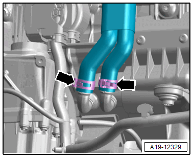
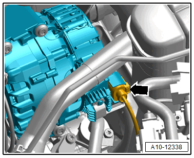
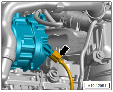
-- Version with dual-clutch transmission: loosen the hose clamp -right arrow-, remove the coolant hose and let the coolant drain.
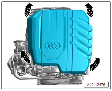
-- Carefully pull the engine cover off the retaining pins one after the other in direction of -arrows-. Do not pull sharply on the engine cover or pull it to one side.
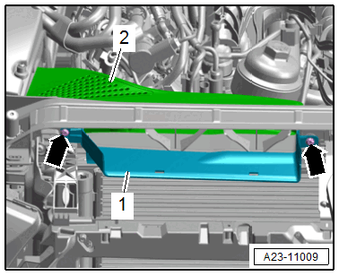
-- Remove the bolts -arrows- and the air guide -2-.
-- If installed, disconnect the connector -2- for the Mass Airflow Sensor - G70-.
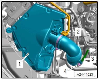 Courtesy of AUDI OF AMERICA, LLC
-- Remove the vacuum hose -3- without damaging it.
-- Loosen the hose clamp -2- and remove the air duct hose.
-- Pull the air filter housing -1- upward.
-- Seal off the turbocharger with plugs that are thoroughly cleaned from the Engine Bung Set: VAS6122 .
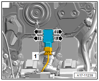
-- Disconnect the fuel hose -1-. Refer to CONNECTOR COUPLINGS, DISCONNECTING .
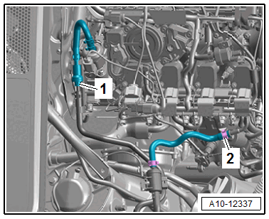
-- Loosen the hose clamp -2- and disconnect the hose for the EVAP system.
-- Seal off any open lines and connections with plugs that are thoroughly cleaned from the Engine Bung Set: VAS6122 .
-- Release the latch in direction of -arrow B- and open the E-box -1- in direction of -arrow A-.
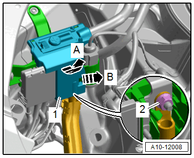
-- Remove the nut -2- and free up the B+ wire.
-- Free up the upper wiring duct.
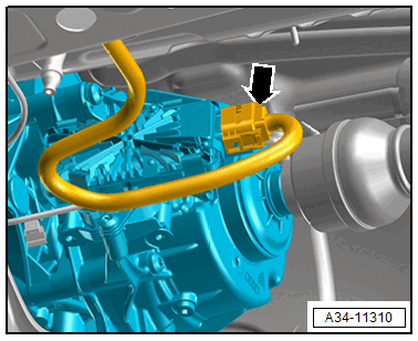
-- Open the heat shield boot.
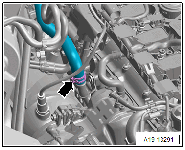
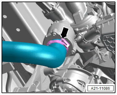
-- Loosen the hose clamp -arrow- and remove the coolant hose.
Version with Catalytic Converters and Particulate Filter:
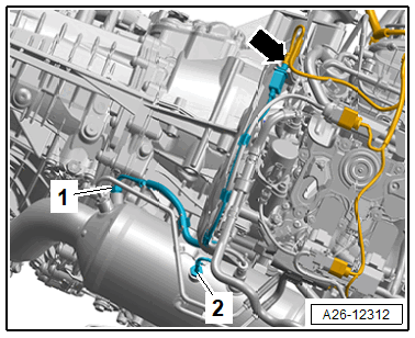
-- Disconnect the connector -arrow- for the Dual Exhaust Temperature Sensor 1 -GX41-.
-- If the engine and transmission are to be separated: remove the connector from the bracket and free up the wires.
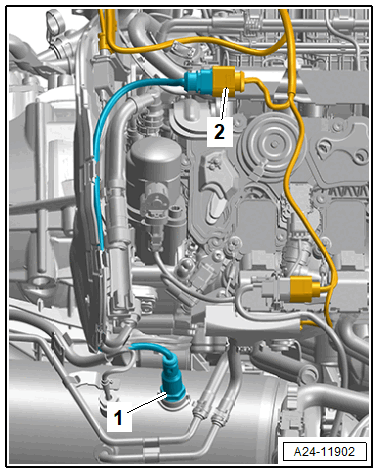
-- Open the heat shield boot.
-- Disconnect the connector -2- for the Particulate Filter Differential Pressure Sensor -G1037-.
-- If the engine and transmission are to be separated, remove the bolt -1- and free up the differential pressure sensor.
Continuation for All Vehicles:
-- Disconnect the connector -2- for Oxygen Sensor 1 after Catalytic Converter -GX7- (example illustration).
-- Version with catalytic converter and particulate filter: if the engine and transmission will be disconnected: remove the connector from the bracket and free up the wires.
-- Disconnect the connector -2- for the Oxygen Sensor 1 before Catalytic Converter -GX10-.
-- Version with catalytic converter and particulate filter: if the engine and transmission will be disconnected: remove the connector from the bracket and free up the wires.
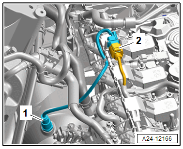
-- If installed, disconnect the connector -1- for the Tank Ventilation Pressure Sensor 1 -G950-, then free up the wire.
-- Free up the wiring harness.
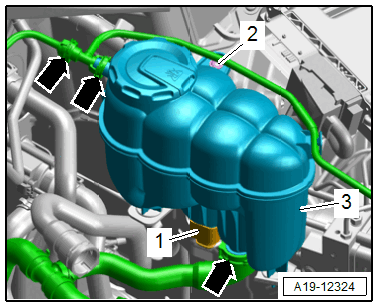
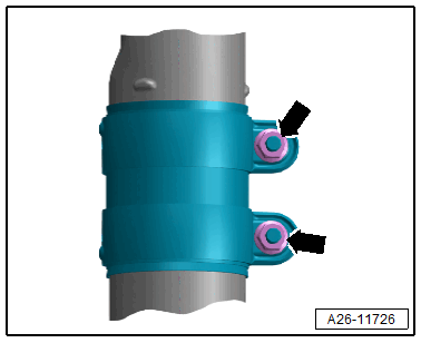
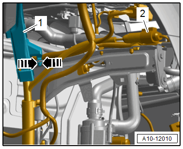
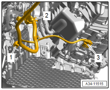
-- Lift the clamps -arrows-, remove and free up the coolant hoses.
-- Disconnect the connector -1- for the Engine Coolant Level Sensor -G32-.
-- Remove the bolt -2- and remove the coolant expansion tank -3-.
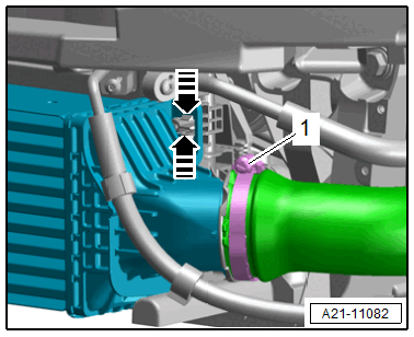
-- Lift the clip -2- and remove the coolant hose from the upper radiator.
-- Lift the clamp -1- and remove the coolant hose.
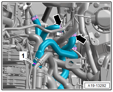
-- Version with dual clutch transmission: loosen the clamps -arrows-, then remove the coolant hoses.
-- Disconnect the connector -arrow- for the Starter Generator -C29-.
-- Disconnect the connector -1- for the Charge Air Pressure Sensor -G31-.
-- Loosen the screw-type clamp -2- and remove the air duct pipe from the Throttle Valve Control Module -GX3-.
-- Release the retainer in direction of -arrow- and remove the vacuum hose -1-.
-- Remove the connector -2- from the bracket and disconnect it.
-- Disconnect the connector -1- from the Engine/Motor Control Module -J623-.
-- Free up the wiring harness and place on the engine.
Version with Catalytic Converters and Particulate Filter:
Risk of injury due to flying soot particles.
Irritation and injury to skin and eyes possible.
- Wear protective eyewear.
- Wear safety gloves.
-- Loosen the screw-type clamp -arrow-.
TIP:
To loosen the screw-type clamp counter with two nuts on the threaded spindle and loosen these.
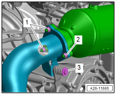
Version with Catalytic Converters without Particulate Filter:
 Courtesy of AUDI OF AMERICA, LLC
-- Remove the nuts -1- from the front muffler accessible from the top.
-- Remove the nut -2- and bolt -3- for the front muffler.
Continuation for All Vehicles:
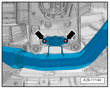
-- Remove the front muffler bolts -arrows-.
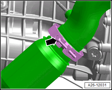
-- Loosen the clamping sleeve -arrows- and push toward the rear.
Risk of damaging the coupling due to improper handling.
- Coupling must not be bent more than 10°.
- Do not load the coupling on the cable.
-- Remove the front muffler.
Version with AWD:
-- Remove the driveshaft. Refer to DRIVESHAFT, REMOVING AND INSTALLING .
-- If equipped, disconnect the connector -arrow- for the All-Wheel Drive Control Module -J492-.
Continuation for All Vehicles:
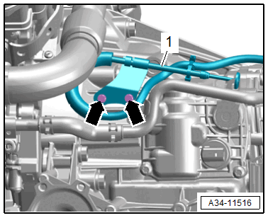
-- Loosen the left and right hose clamp -1- and remove the air duct pipe.
-- Loosen the hose clamp -arrow- and remove the air duct hose at the right from the turbocharger.
-- Remove the connector -2- from the bracket and disconnect it.
-- Release the retainers in direction of -arrows- and free up the wiring duct -1-.
-- Free up the wiring harness to the engine.
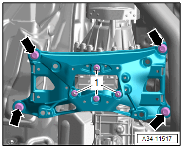
-- Remove the subframe. Refer to SUBFRAME WITH STEERING GEAR, REMOVING AND INSTALLING .
-- Detach the left and right drive axles from the transmission. Refer to DRIVE AXLE, REMOVING AND INSTALLING .
-- Remove the refrigerant lines from the A/C compressor. Refer to REFRIGERANT LINES, REMOVING AND INSTALLING AT A/C COMPRESSOR .
-- Disconnect the connector -arrow- for the A/C compressor.
Version with Manual Transmission:
There is a risk of contamination from the leaking brake fluid.
- Never operate the clutch pedal when the hose/line assembly is removed.
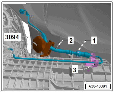
-- Clamp off the hose/line assembly -2- with the Hose Clamps - Up To 25mm: 3094 .
-- Release the clamp -1- using a screwdriver and remove until it stops.
-- Remove the hose/line assembly from the clutch slave cylinder cable.
-- Seal the open lines and connections with clean plugs from the Engine Bung Set: VAS6122 .
-- Remove the nut -arrow- for the gearshift lever.
Risk of damaging the gearshift shaft in the transmission due to improper handling.
- Never pry off or force off the gearshift lever.
- Only remove the gearshift lever with the specified special tools.
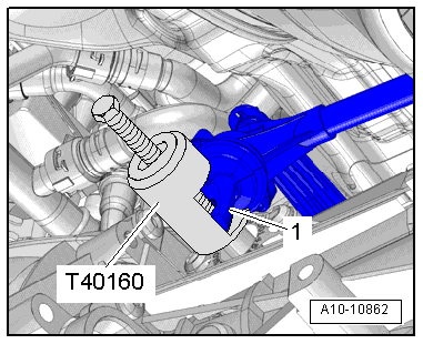
-- Position the Puller - Gear Shaft Linkage: T40160 and remove the gearshift lever -1-.
-- Remove the bolt -1- for the push rod -3- and remove the connecting rod bolt -4-.
-- Disconnect the connector -1- and free up the wire -2- on the tunnel crossmember -arrow-.
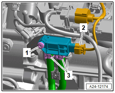
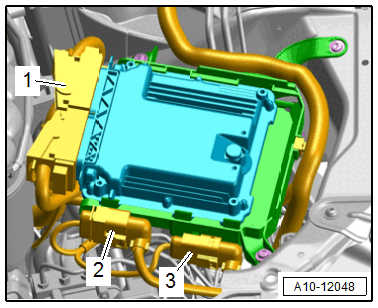
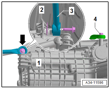
Version with Dual Clutch Transmission:
-- Disconnect the connectors and free up the wires.
1 - For the Parking Lock Solenoid -N486-
3 - For Transmission Electric Pump 2 -V553-
Risk of destroying due to electrostatic discharge.
- Do not touch the connector terminals by hand.
- Touch a ground (for example the hoist) and discharge the static electricity.
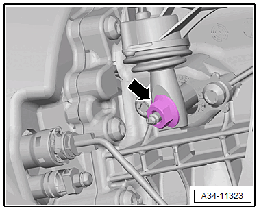
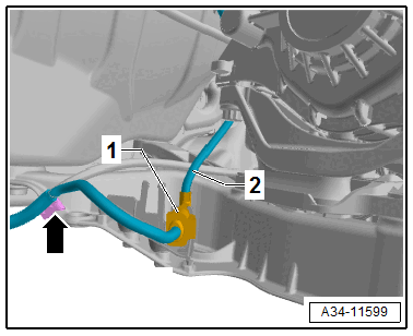
-- Disconnect the connector -2- at the transmission.
-- Remove the bolts -arrows- and free up the parking lock emergency release cable -1-.
If the Engine and Transmission Are to Be Separated for the Subsequent Work, Separate the Drive Plate Threaded Connection at the Torque Converter.
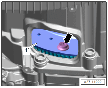
-- Remove the lower cover -1- from the transmission in direction of -arrow-.
-- To do so, use the Wrench - 21mm: T40263 , Adapter: T40314 and 24 mm socket to counterhold the crankshaft at the vibration damper.

Risk of damaging the engine by the timing mechanism skipping.
- Only let the engine turn in the direction of engine rotation.
-- Remove the three bolts -arrow- on the drive plate -1-. Turn the crankshaft an additional 120° in the direction of engine rotation.
Continuation for All Vehicles:
Scissor Lift Table, Preparing:
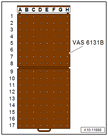
-- Set up the Scissor Lift Table: VAS6131B as follows:
| Table Coordinates | Components from Scissor Lift Table - Audi Set: VAS6131/10 , adapter from Scissor Lift Table - A8 Set - Mounting: VAS6131/11-4 , Scissor Lift Table - A6 Set - Mounting Pins: VAS6131/12-2 and the Threaded Spindle from Scissor Lift Table - Q7 Set: VAS6131/13 | |||
|---|---|---|---|---|
| B7 | /10-1 | /12-2 | Threaded spindle from Scissor Lift Table - Q7 Set: VAS6131/13 | /11-4 |
| G7 | /10-1 | /12-2 | Threaded spindle from Scissor Lift Table - Q7 Set: VAS6131/13 | /11-4 |
| C15 | /10-1 | /10-2 | /10-5 | /10-6 |
| F15 | /10-1 | /10-3 | /10-5 | /10-7 |
-- Secure the mounting elements to the scissor lift table by hand.
-- Position the Scissor Lift Table: VAS6131B horizontally.
- Note the bubble level (sight glass) on support platform.
-- Guide the Scissor Lift Table: VAS6131B under the engine/transmission assembly.
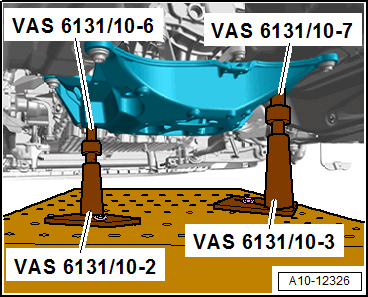
-- Install the mounting elements from the Scissor Lift Table - Audi Set: VAS6131/10 as shown on the tunnel crossmember (example illustration).
-- Pay attention that the right threaded spindle is completely installed (example illustration).
-- Position the mounting elements from Scissor Lift Table - Audi Set: VAS6131/10 , adapter from Scissor Lift Table - A8 Set - Mounting: VAS6131/11-4 , Scissor Lift Table - A6 Set - Mounting Pins: VAS6131/12-2 and the Threaded Spindle -1- from the Threaded Spindle from Scissor Lift Table - Q7 Set: VAS6131/13 to the left and right as shown.
-- Install the bolt -arrow- for the engine mount all the way on the adapter.
-- Rotate the remaining mounting element spindles upward until all the mounting pins come in contact with the mounting points.
-- Tighten the mounting element base plates to 20 Nm on the Scissor Lift Table: VAS6131B .
-- Disengage the Engine Support Bridge - Spindle Engine Support Bridge - Spindle: 10-222A/11 .
-- Remove the bolts -arrows- on the tunnel crossmember (example illustration).
Risk of damaging the lines and hoses, as well as the engine compartment by lowering the engine/transmission assembly.
- Make sure all connections between the engine, transmission and body have been disconnected.
- Carefully lower and guide the engine/transmission assembly out of the engine compartment.
-- Lower the Scissor Lift Table: VAS6131B with the engine/transmission assembly and remove from under the vehicle.