Overview - Turbocharger, Part 1
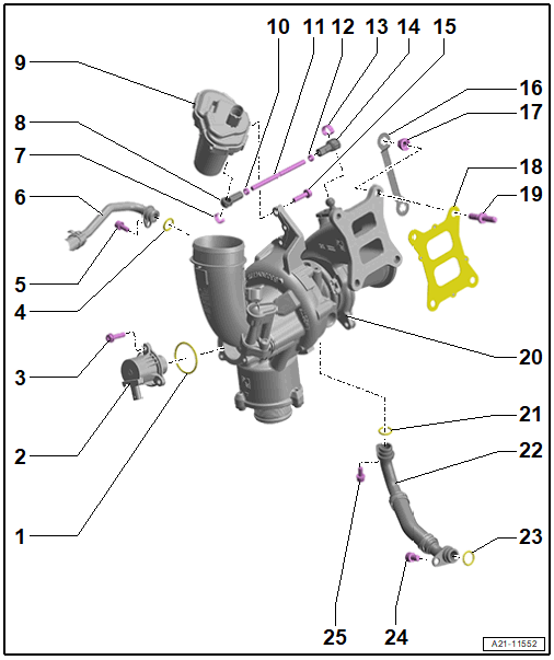
- O-Ring
- Replace after removing
- Turbocharger Recirculation Valve -N249-
- Assembly is only possible in one position because of the offset holes
- Removing and Installing. Refer to Turbocharger Recirculating Valve -N249-, REMOVING AND INSTALLING .
- Bolt
- 9 Nm
- O-Ring
- Replace after removing
- Coat with coolant
- Bolt
- 9 Nm
- Coolant Return Line
- Locking Spring
- Replace after removing
- Ball Socket
- Charge Air Pressure Control Module -GX34-
- Removing and Installing. Refer to Charge Air Pressure Control Module -GX34-, REMOVING AND INSTALLING .
- Nut
- 8 Nm
- Control Rod
- Nut
- 8 Nm
- Locking Spring
- Replace after removing
- Ball Socket
- Bolt
- 8.5 Nm
- Locking Plate
- Replace after removing
- Quantity: 2
- Installing. Refer to Fig 4.
- Nut
- Replace after removing
- Coat the threaded pins with hot bolt paste. Refer to the Electronic Parts Information (ETKA).
- Tightening specification and sequence. Refer to Fig 3.
- Seal
- Replace after removing
- Threaded Pin
- Screw-in depth and tightening specification. Refer to Fig 2.
- Turbocharger
- Removing and Installing. Refer to TURBOCHARGER, REMOVING AND INSTALLING .
- O-Ring
- Replace after removing
- Coat with engine oil
- Oil Return Line
- O-Ring
- Replace after removing
- Coat with engine oil
- Bolt
- 25 Nm
- Bolt
- 9 Nm
Check the Screw-in Depth of the Threaded Pin
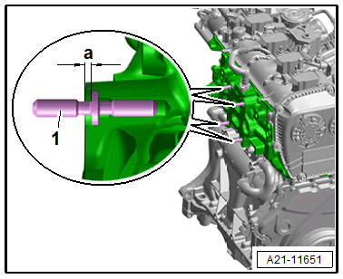
-- Tighten the threaded pin -1- to 23 Nm.
-- Measure the dimension -a- of the sealing surface of the cylinder head to the collar on the threaded pin.
- At dimension -a- less than or equal to 2.4 mm: tightening specification 23 Nm OK
- At dimension -a- more than 2.4 mm: tightening specification 27 Nm.
Turbocharger - Tightening Specification and Sequence
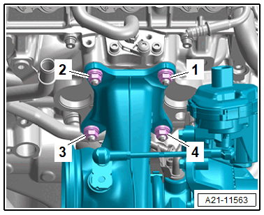
- Replace the nuts after removing.
-- Tighten the bolts in steps in the sequence shown:
| Step | Nuts | Tightening Specifications |
|---|---|---|
| 1. | -1 to 4- | Install all the way by hand |
| 2. | -1 and 2- | 10 Nm |
| 3. | -3 and 4- | 25 Nm |
| 4. | -1 and 2- | 25 Nm |
Install the Locking Plates
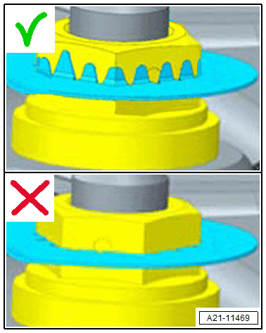
- Pay attention to distortion of the sprockets.
The locking plates are pressed onto the nuts using the following tools:
- Pry bar
- 1 /2 "- EGR Temp. Sensor Socket - 14mm with extension
- Hammer
- Wrench - 14 mm
-- Press on the locking plates for easy accessible nuts using the 1 /2 "- EGR Temp. Sensor Socket - 14mm with extension and the hammer.
-- Press on the locking plates for difficult accessible nuts using the Wrench - 14 mm and the pry bar, at the same time support the pry bar on the turbocharger.