Camshaft, Removing And Installing: Removing
- The cylinder head cover sealing surfaces on the cylinder head must not be worked on.
- During installation, all cable ties must be installed at the same location.
- During installation, all heat shield boots must be installed at the same location.
All except Audi Q7/Q8:
-- Remove the engine cover. Refer to ENGINE COVER, REMOVING AND INSTALLING .
Continuation for All Vehicles:
-- Remove the air filter housing. Refer to AIR FILTER HOUSING, REMOVING AND INSTALLING .
-- Remove the noise insulation (front). Refer to OVERVIEW - NOISE INSULATION .
Vehicle with High-Voltage System:
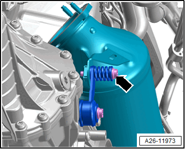
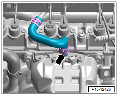
-- Remove the bolt -arrow- from the particulate filter bracket.
Audi A6/A7 with High-Voltage System:
There is a risk of fatal injury due to high voltage.
Electrocution by direct contact or electric arc can cause severe bodily injury or fatal injury.
- Have an Audi high-voltage technician (HVT) or an Audi high-voltage expert (HVE) de-energize the high-voltage system.
-- De-energize the high-voltage system. Refer to HIGH-VOLTAGE SYSTEM, DE-ENERGIZING .
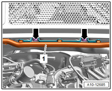
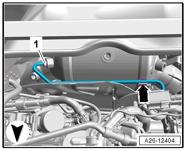
-- Remove the bolts -arrows-, free up the high-voltage cable -1- and slightly press to the front.
Continuation for all Vehicles with High-Voltage System:
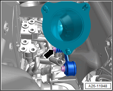
-- Remove the bolt -arrow- from the catalytic converter bracket.
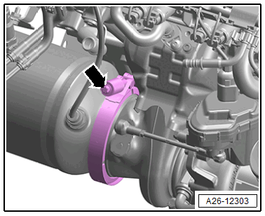
-- Loosen the screw-type clamp -arrow- and push the catalytic converter with particulate filter slightly toward the rear.
Vehicles with Secondary Air System:
-- Remove the resonator for the secondary air system. Refer to SECONDARY AIR SYSTEM RESONATOR, REMOVING AND INSTALLING .
Audi A8/Q7/Q8 with Particulate Filter:
-- Remove the plenum chamber bulkhead. Refer to PLENUM CHAMBER BULKHEAD, REMOVING AND INSTALLING .
Audi Q7/Q8 with Particulate Filter:
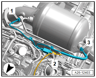
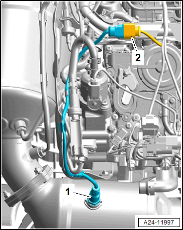
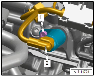
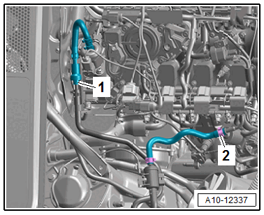
-- Disconnect the connector -2- for the Dual Exhaust Temperature Sensor 1 -GX41-.
-- Remove the connector from the bracket and then free up the wires.
-- Remove the union bolt -1-, free up the pressure pipe on the clip -arrow- and move to the side.
Continuation for All Vehicles:
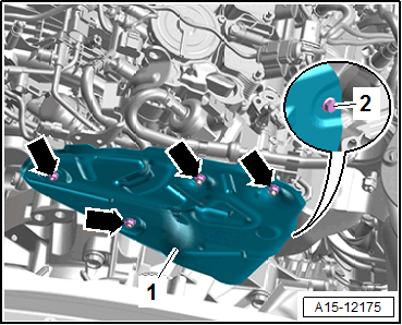
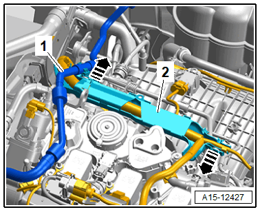
-- Remove the nuts -arrows- and the bolt -2-.
-- Free up the wires and remove the heat shield -1- (example illustration).
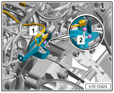
-- Remove the bolts -2- and move the bracket to the side.
-- Remove the upper timing chain cover. Refer to UPPER TIMING CHAIN COVER, REMOVING AND INSTALLING .
-- Disconnect the connector -2- for the Oxygen Sensor 1 After Catalytic Converter -GX7- -1- and free up the wires.
Audi Q7/Q8:
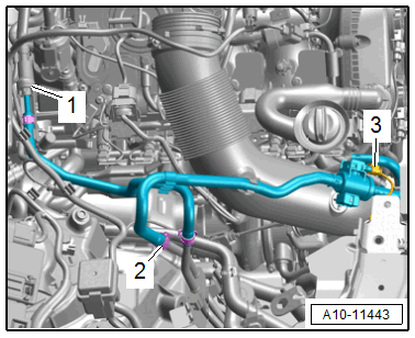
-- Loosen the hose clamp -2- and disconnect the hose for the EVAP system.
-- If installed, disconnect the connector -3- for the Fuel Tank Pressure Sensor 2 -G850-.
-- Remove the vacuum hose -3-.
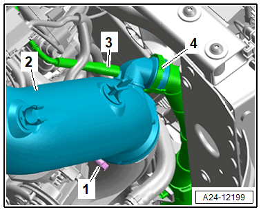
-- Press the release buttons on both sides and remove the secondary air injection hose -4-.
-- Loosen the hose clamp -1- and remove the air duct pipe -2-.
Continuation for All Vehicles:
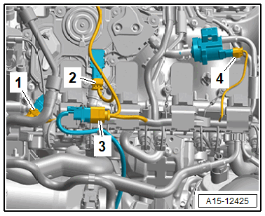
-- Disconnect the connectors and free up the wires.
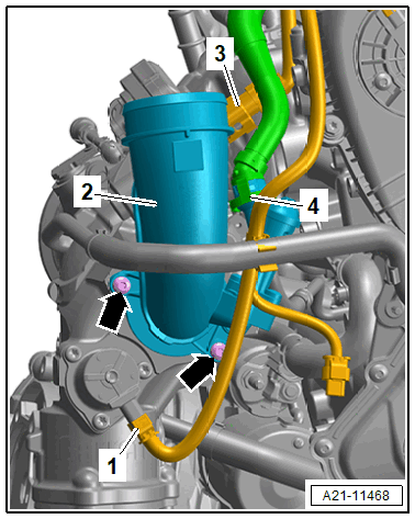
1 -
For the Turbocharger Recirculation Valve -N249-
3 -
for Charge Air Pressure Control Module -GX34-
-- Press the release buttons on both sides and remove the crankcase ventilation hose -4-.
-- Disconnect the connectors and free up the wires.
- For the Camshaft Position Sensor 3 -G300-
- Tank Ventilation Pressure Sensor 1 -G950- (for version)
- For the Oxygen Sensor 1 Before Catalytic Converter -GX10- (remove from the bracket to do so)
- For the EVAP Canister Purge Regulator Valve 1 -N80-
-- Remove the ignition coils. Refer to IGNITION COIL, REMOVING AND INSTALLING .
-- Remove the oil separator. Refer to OIL SEPARATOR, REMOVING AND INSTALLING .
-- Remove the high pressure pump. Refer to HIGH PRESSURE PUMP, REMOVING AND INSTALLING .
-- Remove the vacuum pump. Refer to VACUUM PUMP, REMOVING AND INSTALLING .
-- Open the heat shield boot.
-- Loosen the hose clamp -arrow- and remove the coolant hose.
-- Disconnect the connector -2- from the cam adjustment actuator.
-- Free up the vacuum hose -1- and the wires.
-- Release the catches in direction of -arrows-, remove the wiring duct -2- with the wiring harness and move to the side.
All except Audi Q7/Q8:
-- Loosen the hose clamp -2- and disconnect the hose for the EVAP system.
Continuation for All Vehicles:
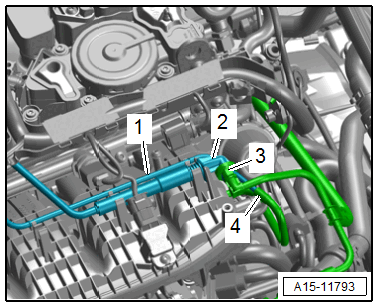
-- Lift the clip -3-, disconnect the coolant line -2- and free up from the cylinder head and push it toward the side.
-- Remove the vacuum hose -4-, disconnect the vacuum line -1- for the Intake Manifold Runner Control Valve -N316- and free it up at the cylinder head.
-- Remove the camshaft timing chain. Refer to CAMSHAFT TIMING CHAIN, REMOVING AND INSTALLING .
-- Apply the oil pump drive chain.
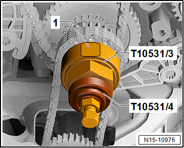
-- Install the Assembly Tool - Turning Over Tool: T10531/3 . In the "TDC point" the flat area -1- points upward. Install the Assembly Tool - Knurled Nut: T10531/4 . Turn the crankshaft with a 32 mm open end wrench 90° counter-clockwise out of "TDC".
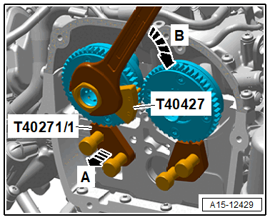
-- Reduce the intake camshaft pretension using the Assembly Tool: T40427 in the direction of -arrow B-, pull the Camshaft Lock: T40271/2 out of the chain sprocket splines in direction of -arrow A-, and bring the intake camshaft into its resting position.
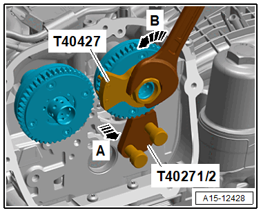
-- Reduce the exhaust camshaft pretension using the Assembly Tool: T40427 in the direction of -arrow B-, pull the Camshaft Lock: T40271/1 out of the chain sprocket splines in direction of -arrow A-, and bring the intake camshaft into its resting position.
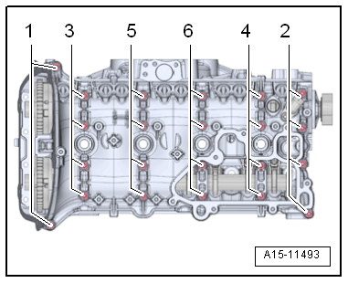
-- Remove the cylinder head cover bolts in -1 to 6- sequence.
-- Carefully loosen the cylinder head cover -2- from the bonding with a screwdriver -1- and remove it together with the camshafts.
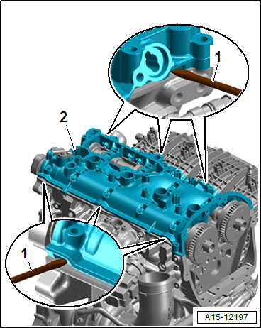
- Pay attention that the camshafts do not fall out of the cylinder head cover.
-- Remove the camshaft and cover the open engine components.
-- If necessary for continuing work: mark the roller rocker lever and hydraulic lifter for reinstallation, remove them and place on a clean surface.