Overview - ATF Circuit: Notes
NOTE:
The 7-speed dual-clutch transmission is equipped with an ATF and MTF chamber.
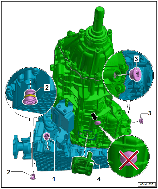
The ATF is located in the blue section of the transmission and is drained through the ATF drain plug -1- and filled through the ATF filler plug -2-. Refer to ATF .
The MTF is located in the green section of the transmission fluid and is drained by removing the MTF pump -4- and is filled through the MTF check plug -3-. Refer to TRANSMISSION FLUID, DRAINING AND FILLING .
The bolt on the gear set -arrow- is not a drain plug.
CAUTION:
Risk of damaging the transmission.
- Remove all the plugs on the ATF lines and on the transmission that were installed during removal.
- The ATF cooling function will not work and the transmission will be damaged if the plugs are forgotten.
WARNING:
The system is under pressure.
- Deactivate the ATF pump and drain the hydraulic pressure reservoir before opening the ATF circuit!
- Also refer to ATF PUMP, DEACTIVATING AND DRAINING THE HYDRAULIC PUMP RESERVOIR .
ATF Cooler, ATF Line
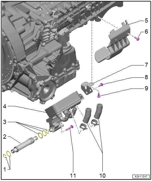
- O-Rings
- Replace after removing
- ATF Pipe
- Replace after removing
- O-Rings
- Replace after removing
- ATF Cooler
- Removing and Installing. Refer to ATF COOLER, REMOVING AND INSTALLING .
- Guard Plate
- Depending on the version
- Bolt
- 8 Nm
- Bracket
- Bolt
- Tightening specification and sequence. Refer to Fig 3.
- Replace after removing
- Bolt
- Tightening specification and sequence. Refer to Fig 3.
- Replace after removing
- Coolant Hoses
- Bolt
- Tightening specification and sequence. Refer to Fig 3.
- Replace after removing
ATF Cooler - Tightening Specification and Sequence
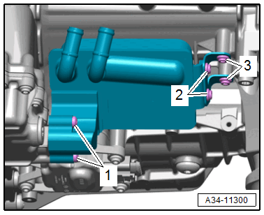
-- Tighten the bolts in steps according to the specified sequence:
| Step | Bolts | Tightening Specification/Additional Turn |
|---|---|---|
| 1. | -1- | Install all the way by hand |
| 2. | -1- | 3 Nm +90° |
| 3. | -2 and 3- | Install all the way by hand |
| 4. | -2 and 3- | 3 Nm + 60° |