Camshaft Timing Chain, Removing And Installing: Installing
Requirements:
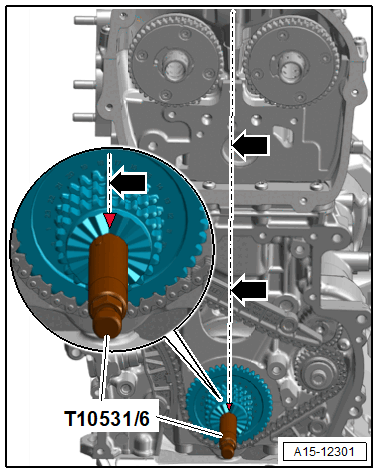
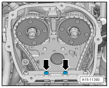
- The crankshaft is at "TDC" ; the v-shaped cut-out on the three-layer chain sprocket points in an imaginary vertical line -arrows- centered between the camshaft chain sprockets.
- Three-layer chain sprocket locked with the : T10531/6 .
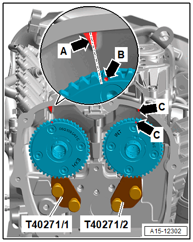
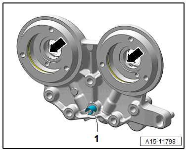
- Camshaft chain sprockets locked at "TDC" using the : T40271/1
and : T40271/2
.
- The marking -arrow B- at the exhaust camshaft must be shifted by half a tooth clockwise to the marking -arrow A- at the cylinder head cover.
- The marks -arrows C- must be positioned opposite each other.
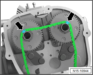
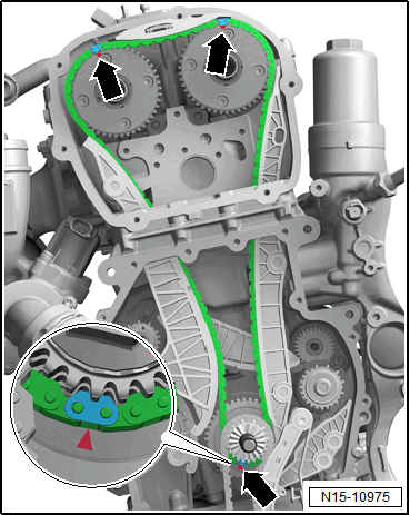
-- Engage the camshaft timing chain with the painted links -arrows- on the camshaft pins as shown.
-- Camshaft timing chain on intake camshaft; mount the exhaust camshaft and the three-layer chain sprocket.
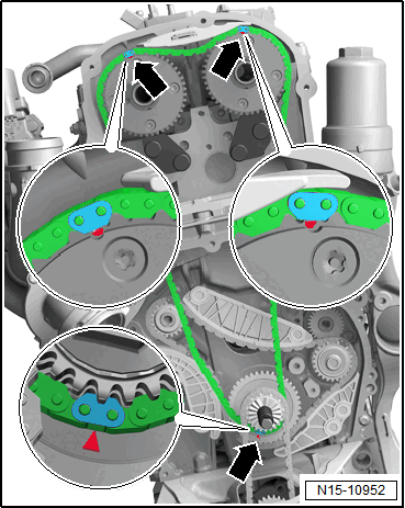
- The painted chain links must align with the markings on the chain sprockets -arrows-.
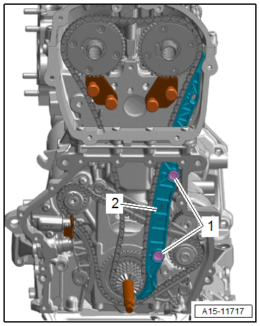
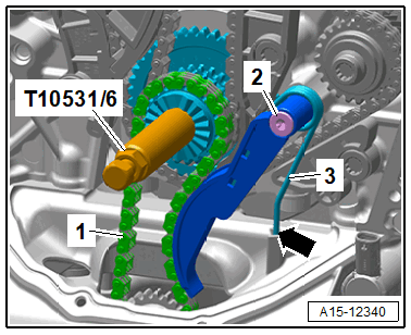
-- Insert the guide rail -2- and tighten the guide pin -1-.
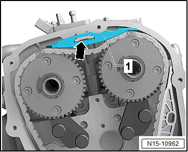
-- Engage the upper guide rail -1- into the retainer -arrow-.
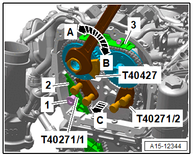
-- Lower the pretension of the exhaust camshaft using the : T40427 in direction of -arrow B- and remove the : T40271/1 from the splines of the chain sprocket in direction of -arrow C-.
-- Remove the exhaust camshaft in the direction of -arrow A- until the timing chain touches the guide rail -3-.
-- Hold the camshaft in this position, insert the tensioning rail -2- and tighten the guide pin -1-.
-- Remove the : T40271/1 .
-- Reduce the intake camshaft pretension using the : T40427 in the direction of -arrow A-, pull the : T40271/2 out of the chain sprocket splines in direction of -arrow B-, and bring the camshaft into its resting position.
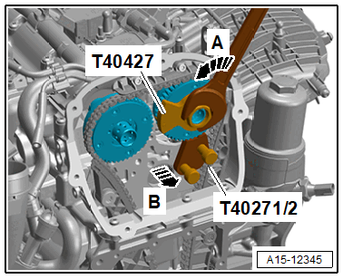
-- Remove the : T40271/2 .
-- Install the bolts -arrows- and tighten them. Tightening specification. Refer to -item ) Bolt.
-- Coat the holes -arrows- with engine oil.
-- Check if the adapter sleeve -1- is installed.
-- If the bearing bracket should be reused, then the adapter sleeve must be driven back.
- The adapter sleeve must be flush in the housing of the bearing bracket.
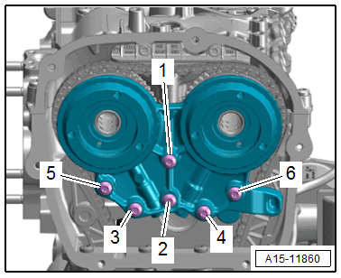
-- Attach the bearing mount and install the bolts -1 to 6- all the way by hand.
-- Remove the : T40435 .
-- Tighten the bearing bracket bolts (refer to Figure), at the same time the adapter sleeve is pulled into the cylinder head with the bolt -2-.
-- Checking adjustment:
 Courtesy of AUDI OF AMERICA, LLC
- The painted chain links must align with the markings on the chain sprockets -arrows-.
-- Install the control valves -item ) Control Valve.
-- Apply the oil pump drive chain.
-- Insert the chain tensioner and tighten the guide pin -2-.
-- Engage the tension spring wire clip -3- to the cut-out at the oil pan upper section -arrow-.
Risk of damaging the engine by the timing mechanism skipping.
- Only let the engine turn in the direction of engine rotation.
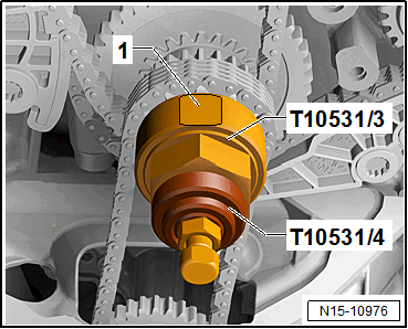
-- Install the : T10531/4 and the : T10531/3 .
Risk of damaging the valves and piston crowns by performing procedures on the valvetrain.
- To ensure valves do not strike pistons when starting, carefully rotate the crankshaft at least two turns.
-- Turn the engine twice in the direction of engine rotation.
TIP:
Due to the ratio, the painted chain links no longer match up after the engine has been turned.
-- Remove the knurled nut and the turning over tool.
Install in reverse order of removal. Note the following:
-- Lower Timing Chain Cover, Replacing. Refer to LOWER TIMING CHAIN COVER, REPLACING .
-- Upper Timing Chain Cover, Replacing. Refer to UPPER TIMING CHAIN COVER, REMOVING AND INSTALLING .