Led Headlamp, Adjusting, Before Product Improvement: Procedure
-- Turn on the low beams (but not set at "Auto").
-- Connect the Vehicle Diagnostic Tester.
-- Select and start the Diagnostic operating mode.
-- Select the Test plan tab.
-- Select the Select individual test button and select the following tree structure consecutively:
- Vehicle functionality
- Adjusting/calibrating headlamps
TIP:
When this program is selected, the suspensions moves into the air suspension normal level and the headlamps go into basic setting.
-- Start the selected program and follow the instructions on the Vehicle Diagnostic Tester display.
-- During the program, it will be asked to perform a headlamp adjustment.
TIP:
The image and the following description apply to analog headlamp adjusting units. On digital headlamp adjusting units, for example Approved Alignment & Adjustment Unit, follow the operating instructions. Refer to Headlamp Adjusting Unit Operating Instructions.
The headlamp adjusting unit must be aligned to the vehicle.
-- To do this, slide the headlamp adjusting unit a distance of 100 mm centered in front of the vehicle and aligned to the vehicle front. Refer to Headlamp Adjusting Unit Owner's Manual.
-- Slide the headlamp adjusting unit in front of the corresponding headlamp and check the alignment again.
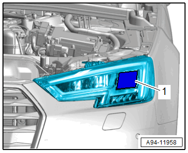
-- The headlamp adjusting unit must be aligned at the center of the marked reflector segment -1-.
- The horizontal cut-off line must touch the cut-off line -1- on the adjusting unit test surface.
- The bend point -2- between the left horizontal part and the right rising part of the cut-off line must run vertically through the central mark -3-. The bright core of the light beam must be to the right of the vertical.
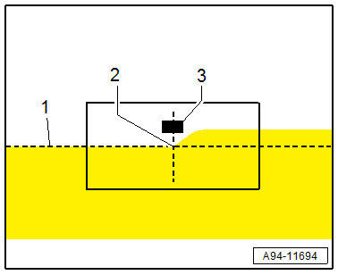
- After adjusting the low beam according to the instructions, the center of the high beam light beam must be on the central marking -3-.
-- To adjust the height of the headlamp -1-, first set the cut-off line just under the dividing line with the adjustment screw -2-.
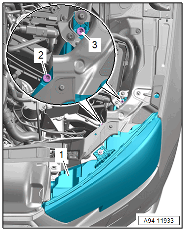
-- Then adjust the cut-off line on the dividing line starting from the bottom.
-- For side adjustment, turn the adjusting screw -3-.
TIP:
The right headlamp layout is a mirror image.
-- After successful headlamp adjustment, follow the instructions on the display of the Vehicle Diagnostic Tester.
-- Disconnect the data link connector.