Matrix Led Headlamp, Adjusting/Calibrating, From Product Improvement: Procedure
-- Turn on the low beams (but not set at "Auto").
-- Connect the Vehicle Diagnostic Tester.
-- Select and start the Diagnostic operating mode.
-- Select the Test plan tab.
-- Select the Select individual test button and select the following tree structure consecutively:
- Vehicle functionality
- Adjusting/calibrating headlamps
TIP:
When this program is selected, the suspensions moves into the air suspension normal level and the headlamps go into basic setting.
-- Start the selected program and follow the instructions on the Vehicle Diagnostic Tester display.
-- During the program, it will be asked to perform a headlamp adjustment.
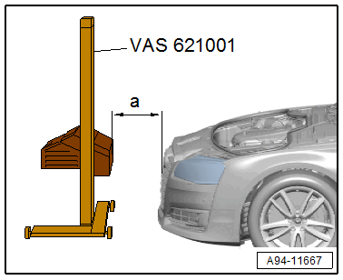
-- Align the Approved Alignment & Adjustment Unit at the distance -a- = 100 mm to the vehicle center. Refer to the Approved Alignment & Adjustment Unit Owner's Manual.
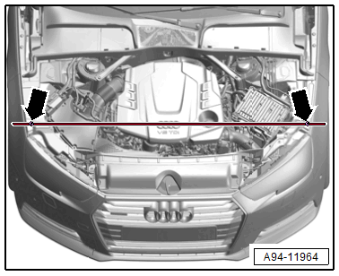
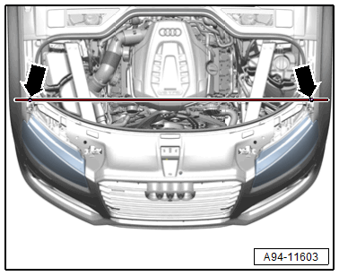
-- Check the parallel alignment of the Approved Alignment & Adjustment Unit to the vehicle transverse axis by aligning the Approved Alignment & Adjustment Unit laser beam on the left and right front fender bolts -arrows-.
- To prevent a glare for other motorists, pay attention to the exact orientation of the headlamp adjusting unit.
-- Push the Approved Alignment & Adjustment Unit in front of the left headlamp and check the parallel alignment again.
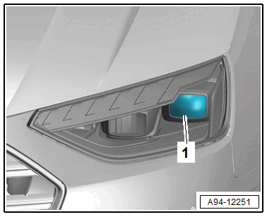
-- Align the Approved Alignment & Adjustment Unit centered to the indicated segment -1-.
-- Press the "OEM" button -arrow- on Approved Alignment & Adjustment Unit in the main menu.
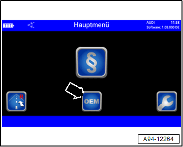
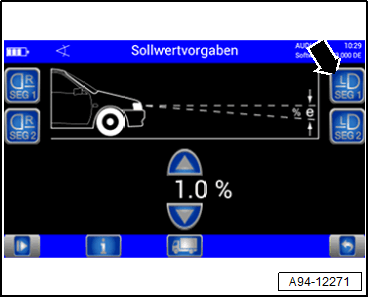
-- Select "Audi" -arrow-.
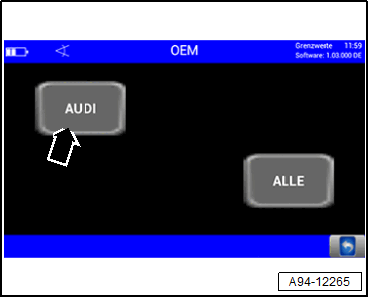
Shown on display:
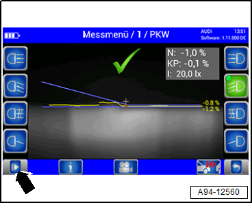
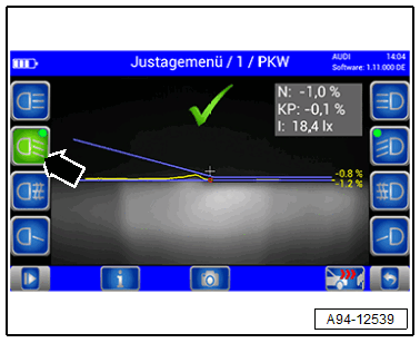
-- Press the button -arrow- for the left low beam headlamp.
-- Wait until the light measurement is complete.
-- To adjust the height of the headlamp -1-, first set the cut-off line just under the dividing line with the adjustment screw -2-.
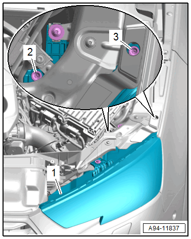
-- Then adjust the cut-off line on the dividing line starting from the bottom.
-- For side adjustment, turn the adjusting screw -3-.
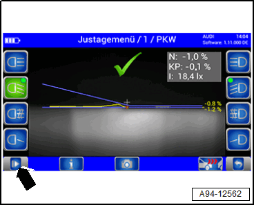
-- After successful adjustment of the low beams press the left button -arrow-.
A reference segment is activated as the program sequence continues.
-- Position the Approved Alignment & Adjustment Unit centered to the headlamp reference segment.
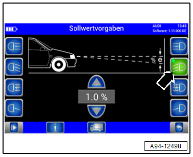
Shown on display:
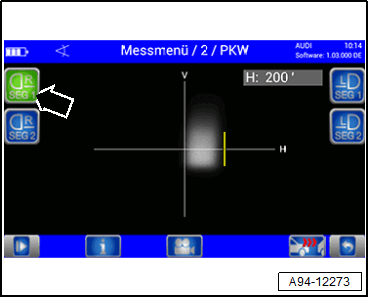
-- Press the button -arrow- for Matrix beam 1.0.
-- Wait until the light measurement is complete.
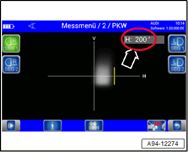
Shown on display:
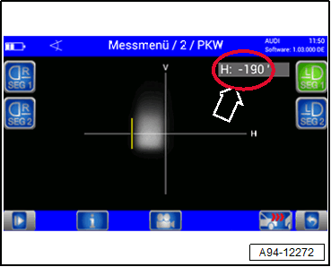
- The angle value of the edge of the inner reference segment for the left headlamp is shown.
-- Enter the angle value -arrow- of the inner reference segment edge in the Vehicle Diagnostic Tester. While doing so, pay attention to the sign if necessary.
Shown on display:
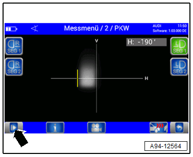
-- Press the button -arrow-.
The program sequence will require that the Approved Alignment & Adjustment Unit from the left side to the right side.
-- Align the Headlamp Adjusting Unit Approved Alignment & Adjustment Unit at the distance -a- = 100 mm to the vehicle center. Refer to the Approved Alignment & Adjustment Unit Owner's Manual.
-- Check the parallel alignment of the Approved Alignment & Adjustment Unit to the vehicle transverse axis by aligning the Approved Alignment & Adjustment Unit laser beam on the left and right front fender bolts -arrows-.
-- Push the Approved Alignment & Adjustment Unit in front of the right headlamp to check the parallel alignment again.
-- Align the Approved Alignment & Adjustment Unit centered on the low beams reflector segment.
Shown on display:
-- Press the button -arrow- for the right low beam headlamp.
-- Wait until the light measurement is complete.
-- Adjust the right headlamp low beams the same way as the left headlamp.
Shown on display:
-- After successful adjustment of the low beams press the right button -arrow-.
A reference segment is activated as the program sequence continues.
-- Position the Approved Alignment & Adjustment Unit centered to the headlamp reference segment.
Shown on display:
-- Press the button -arrow- for Matrix beam 1.0.
-- Wait until the light measurement is complete.
Shown on display:
- The angle value of the edge of the inner reference segment for the right headlamp is shown.
-- Enter the angle value -arrow- of the inner reference segment edge in the Vehicle Diagnostic Tester. While doing so, pay attention to the sign if necessary.
-- After completing the calibration, read the DTC memory and correct any existing faults.