Lane Change Assistance, Calibrating
Special tools and workshop equipment required
- Vehicle Diagnostic Tester
- Calibration Unit :VAS6350A
Conditions
-- The Lane Change Assistance Control Module -J769- / Lane Change Assistance Control Module 2 -J770- must be calibrated using the Vehicle Diagnostic Tester during the following conditions:
- Lane Change Assistance Control Module -J769- or Lane Change Assistance Control Module 2 -J770- was replaced.
- The rear bumper cover was damaged by a parking block, for example.
- The rear bumper cover was removed and installed.
- The threaded connections on the bumper mount are loosened.
- "No or incorrect basic setting/adaptation" is stored in the DTC memory.
Preparing for Calibration
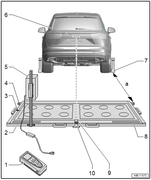
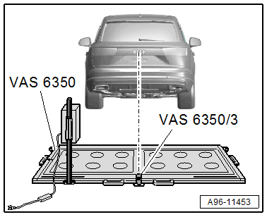
- Calibration Tool - Spacing Laser :VAS6350/2
- For distance measurement
- Usage information. Refer to the Calibration Tool :VAS6350 Owner's Manual.
- Calibration Tool :VAS6350A
- Level
- On the :VAS6350A
- To check the horizontal position of the :VAS6350A
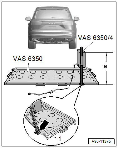
- Catch Bracket
- To mount the :VAS6350/2 for the distance measurement
- Distance to the :VAS6350/1 on the rear wheels: Dimension -a- = 1700 ± 2 mm
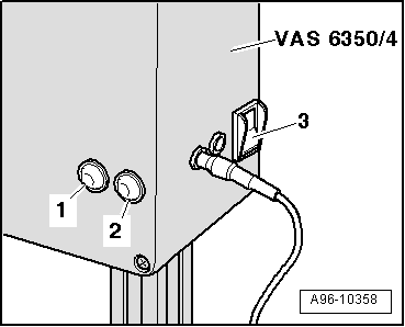
- Calibration Tool - Lane Change Calibration Tool :VAS6350/4
- Is moved from one side of the measuring field to the other during calibration
- When installed correctly, the vehicle electrical system voltage line must be connected at lower left of the calibration device (as seen in direction of travel)
- Brand Emblem
- The laser point is aligned to the center of the brand emblem
- Calibration Tool - Wheel Center Mountings :VAS6350/1
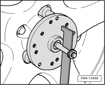
- With wheel bolt adapter and measuring paddle
- Measuring Scale
- For positioning the :VAS6350/4
- Calibration Tool - Linear Laser :VAS6350/3
- With "laser protective eyewear"
- On the :VAS6350A
- Switching on and off. Refer to :VAS6350A Owner's Manual.
- Plastic Foot
- Can be adjusted when setting the horizontal position of the :VAS6350A
- Quantity: 3
Preliminary Work
-- Move the vehicle onto a solid, flat surface.
-- Activate the "standard vehicle height" on vehicles with air suspension (MMI setting: Automatic or comfort).
-- Apply the parking brake - the vehicle must not move during the measurement.
-- Place the front wheels in a straight-ahead position - steering wheel in neutral position.
-- Connect the Vehicle Diagnostic Tester.
TIP:
If a malfunction message appears in the display. Refer to the Vehicle Diagnostic Tester Operating Instructions.
-- Switch the ignition on.
-- Remove the label with the metal foil from the bumper cover, if necessary.
-- Secure three suitable wheel bolt adapters for the wheel bolts on each :VAS6350/1 .
 Courtesy of AUDI OF AMERICA, LLC
-- Insert the measuring paddle at both :VAS6350/1 and secure with the locking nut.
-- Place the :VAS6350/1 onto the wheel bolts on both rear wheels.
- The wheel center mounting rotation center must be in the wheel rotation center.
-- Place the :VAS6350/1 on the wheels so that the "anti-theft wheel bolts" are not connected to the wheel center mounting.
-- Adjust the measuring paddle using the locking nuts so that they move freely just above the floor.
- The measuring paddles must move easily.
- The measuring paddles must be vertical.
-- Position the :VAS6350A at distance -a- to the rear wheels.
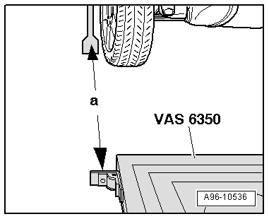
- Dimension -a- = 1, 700 mm (66.92 in.)
-- Switch on the :VAS6350/2 with the ON button.
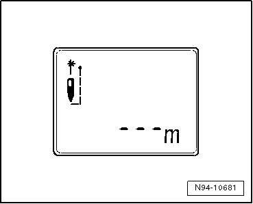
Display on the :VAS6350/2 :
- "- - - m"
- The laser is switched on at same time.
-- For distance measurement, hold the :VAS6350/2 -2- flush to the left catch bracket as shown.
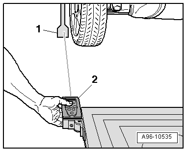
- The :VAS6350/2 must lie firmly against the catch bracket.
-- Make sure the "laser beam" for the distance measurement contacts the enlarged lower part on the paddle -1-.
If this is not the case, measuring paddle height must be corrected using locking nuts on :VAS6350/1 .
-- Briefly press the ON button for distance measurement.
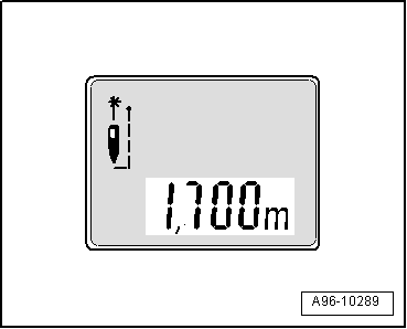
Display on the :VAS6350/2 :
- "1, 700 m" (specified value: 1700 ± 2 mm).
-- Repeat the measuring procedure from the right stop bracket to the right rear wheel.
- The distance value must be the same on both sides.
If both measured values are not the same, adjust the :VAS6350A accordingly.
Calibrating Procedure
The Vehicle Diagnostic Tester is connected.
-- Select and start the Diagnostic operating mode.
-- Select the Test plan tab.
-- Select the Select individual test button and select the following tree structure consecutively:
- Body
- Electrical system
- 01 - OBD-capable systems
- CF - Lane Change Assistance Control Module 2 -J770
- CF - Lane Change Assistance Control Module 2, Functions
- CF - Calibration
-- Start the selected program and follow the instructions on the Vehicle Diagnostic Tester display.
TIP:
- The following information clarifies which version of the lane change assistance is installed in the vehicle (SWA3.0).
-- Secure the :VAS6350/4 to the :VAS6350A mount on the rear left.
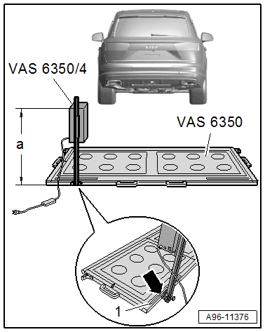
- When installed correctly, the vehicle electrical system voltage wire must be connected at the bottom left of the calibration device (as seen in direction of travel).
Dimension -a- is measured from the upper edge of the calibration device to the floor.
| Model | A4/S4 Sedan | A4/S4/RS 4 Avant | A4 allroad |
|---|---|---|---|
| Adjustment dimension height in mm dimension -a- | 815 | 800 | 836 |
-- The indicator on the base of the :VAS6350/4 must align with adjustment dimension on the measuring scale -1- on measuring field -arrow-.
| Model | A4/S4 Sedan | A4/S4/RS 4 Avant | A4 allroad |
|---|---|---|---|
| Left adjustment dimension read in mm on the measuring scale -1- | 709 | 714 | 714 |
-- Connect the :VAS6350/4 to the vehicle electrical system voltage.
-- Bring the :VAS6350A into a horizontal position by turning the plastic feet.
 Courtesy of AUDI OF AMERICA, LLC
- Observe the bubble level (sight glass) on the :VAS6350A -arrow-.
-- Turn on the :VAS6350/3A on the :VAS6350A .
-- Wear "laser protective eyewear".
-- Align the :VAS6350A so that the :VAS6350/3A strikes the center of the brand emblem on the rear lid.
-- Check the distance on the left and right sides between the catch brackets of the :VAS6350A and the measuring paddles -1- on wheel mountings again.
- Specified value: 1700 ± 2 mm
Calibration Procedure
The following should not occur during the calibration procedure:
- There must be no metal reflectors within a 2 m radius of the calibration device (for example, tool carts, metal cabinets).
- Vehicle doors must not be opened or closed.
- People must not sit in the vehicle.
- People must not go between the vehicle and the :VAS6350/4 .
Procedure
 Courtesy of AUDI OF AMERICA, LLC
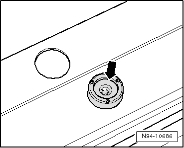
-- Turn on the :VAS6350/4 at the power switch -3-.
- The green LED -1- must turn on.
-- If the red LED -2- turns on: Check the :VAS6350/4 .
-- Follow the instructions in the Vehicle Diagnostic Tester display.
During the program sequence, there is a prompt to switch the :VAS6350/4 from the left to the right side of the :VAS6350 .
-- Turn off the :VAS6350/4 and reposition the calibration tool.
- When installed correctly, the vehicle electrical system voltage wire must be connected at the bottom left of the calibration device (as seen in direction of travel).
Dimension -a- is measured from the upper edge of the calibration device to the floor.
| Model | A4/S4 Sedan | A4/S4/RS 4 Avant | A4 allroad |
|---|---|---|---|
| Adjustment dimension height in mm dimension -a- | 815 | 800 | 836 |
-- The indicator on the base of the :VAS6350/4 must align with adjustment dimension on the measuring scale -1- on measuring field -arrow-.
| Model | A4/S4 Sedan | A4/S4/RS 4 Avant | A4 allroad |
|---|---|---|---|
| Right adjustment dimension read in mm on the measuring scale -1- | 709 | 714 | 714 |
-- Turn on the :VAS6350/4 at the power switch -3-.
Courtesy of AUDI OF AMERICA, LLC- The green LED -1- must turn on.
-- Follow the instructions in the Vehicle Diagnostic Tester display.
-- After calibrating the lane change assistance successfully, end "calibration", switch off the ignition and disconnect the data link connector.