9VS - Premium Sound System, Bang & Olufsen
- Two speakers in the left and right A-pillars
- Two speakers in the left and right front doors
- One speaker on the left and right side of the instrument panel
- Two speakers in the center of the instrument panel
- Two speakers in the left and right rear doors
- Two speakers in the rear shelf/left and right D-pillar
- Subwoofer -R211-
- Digital Sound System Control Module -J525- in luggage compartment on left rear side
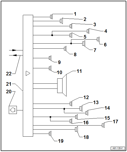
- Left Front Treble Speaker 2 -R220- in the left A-pillar at the top
- Left Front Midrange Speaker 2 -R276- in the Instrument Panel on the Left Side
- Left Front Bass Speaker -R21- in the bottom of the left front door
- Left Front Midrange Speaker -R103- in center of left front door
- Left Front Treble Speaker -R20- in the left upper a-pillar
- Left Rear Treble Speaker -R14- in Left Rear Door at Top
- Left Rear Bass Speaker -R15- in the bottom of the left rear door
- Left Effects Speaker -R209- in the Rear Shelf/Left D-Pillar
- Center Speaker -R208- in the Center Instrument Panel
- Center Speaker 2 -R219- in the Center of the Instrument Panel
- Subwoofer -R11- in the Rear Shelf/Luggage Compartment Recess
- Right Effects Speaker -R210- in the Rear Shelf/D-Pillar on the right side
- Right Rear Bass Speaker -R17- in the bottom of the right rear door
- Right Rear Treble Speaker -R16- in the right rear door at the top
- Right Front Treble Speaker -R22- in the Right Upper A-Pillar
- Right Front Midrange Speaker -R104- in center of right front door
- Right Front Bass Speaker -R23- in the bottom of the right front door
- Right Front Midrange Speaker 2 -R277- in the instrument panel on the right side
- Right Front Treble Speaker 2 -R221- at the top of the right A-pillar
- Interior Microphone -R74-, Microphone Unit in Front Roof Module -R164- in the Front Interior Lamp -W1-
- Digital Sound System Control Module -J525- in luggage compartment on left rear side
- MOST Bus
Notes on MOST Bus
The optical data bus "MOST bus" is used in addition to the CAN bus.
A fiber-optic cable is used. Fiber optic cables are routed inside corrugated tubes for protection.
Replace the complete fiber-optic cable if possible.
The front surface of the connectors must not be contaminated.
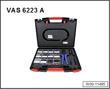
If disconnecting the connectors: Attach the Fiber-Optic Repair Set - Connector Protective Caps: VAS 6223/9 .
When routing fiber-optic cables, make sure not to go below the minimum bending radius of 25 mm. Do not crush or kink the fiber-optic cables.
Repairing fiber optic cables. Refer to FIBER-OPTIC CABLES, REPAIRING .