Control Arm, Removing And Installing: Installing
Install in reverse order of removal and Note The Following:
-- When reusing the ball joint, clean any remaining locking compound residue off the pin threads.
-- Bring the control arm with the ball joint into the installation position.
There is a risk of damage occurring in the threaded connection area on the wheel bearing housing if the installation position is incorrect.
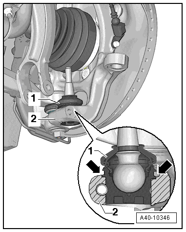
- INSERT THE BALL JOINT -1- INTO THE WHEEL BEARING HOUSING -2- UP TO THE CONTACT SURFACE -ARROWS-.
-- Install the threaded connections for the components with bonded rubber bushings only until the stop, but do not tighten yet.
Bonded rubber bushings have a limited range of rotation. Only tighten the threaded connections for the suspension when the vehicle is in curb weight position.
-- Lift the wheel bearing in curb weight position. Refer to WHEEL BEARING IN CURB WEIGHT POSITION, LIFTING VEHICLES WITH COIL SPRING .
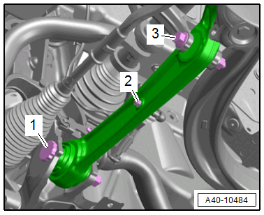
-- When tightening the threaded connection -1-, the control arm must be pressed toward the inside of the vehicle.
- Overview table for when an axle alignment is needed. Refer to NEED FOR AXLE ALIGNMENT, EVALUATING .
- Adjust the headlamps. Refer to HEADLAMP, ADJUSTING .
- Driver assistance systems front camera, calibrating. Refer to DRIVER ASSISTANCE SYSTEMS FRONT CAMERA, CALIBRATING .