Spring, Removing And Installing: Removing
FWD Vehicles:
-- Remove the rear wheel. Refer to WHEELS AND TIRES .
-- Remove the expanding rivets -2-.
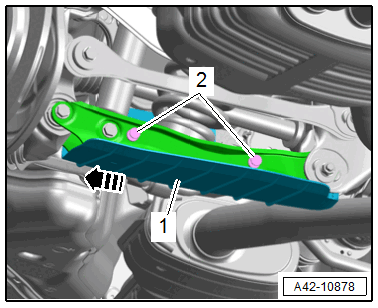
-- Pull the wind deflector -1- slightly outward in direction of -arrow- and remove.
AWD Vehicles, Right Side of the Vehicle
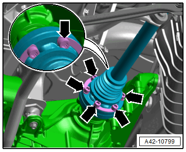
-- Remove the bolts -arrows- on the inner CV joint and press the inside of the drive axle upward.
AWD Vehicles, Left Side of the Vehicle
-- Remove the heat shield.
-- Remove the bolts on the inner CV joint and press the inside of the drive axle upward.
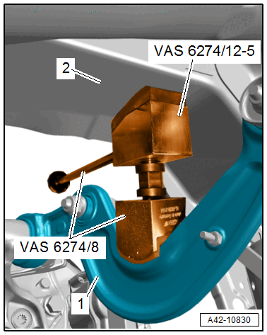
-- Place the spreader device, consisting of :VAS6274/8 and :VAS6274/12-5 , between the front upper transverse link -1- and the longitudinal member -2- as shown, and pretension slightly.
-- Press the locking plate -2- outward in the direction of the -arrow A- (open).
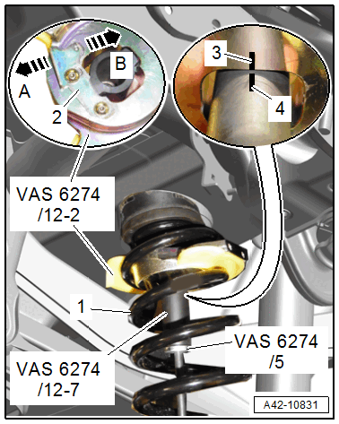
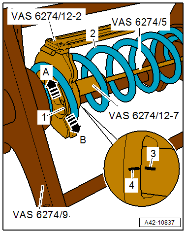
-- Insert the :VAS6274/12-2 as shown from the outside into the coil spring -1-.
-- Insert the :VAS6274/12-7 with the :VAS6274/5 into the thrust plate and turn 90° until the line marking -3- on the thrust plate is flush with the line marking -4- on the plunger.
-- Pull the plunger downward into the thrust plate and secure with the locking in the direction of the plate in direction of -arrow B- (close).
-- Remove the :VAS6274/5 .
 Courtesy of AUDI OF AMERICA, LLC
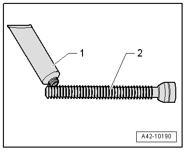
There is a risk of damaging the spindle due to missing or incorrect grease.
- Coat the front area of the :VAS6274/3 -2- lightly with the accompanying grease -1- before removal and installation of each spring.
-- Insert the :VAS6274/12-1 as shown from the outside into the coil spring -arrow-.
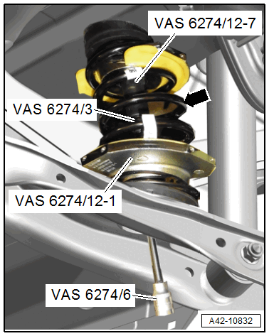
-- Lightly lubricate the :VAS6274/3 in the front area and screw loosely into the :VAS6274/12-7 using the :VAS6274/6 .
Risk of accident!
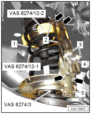
- The coil spring may only be tensioned or released if the locking device brackets -2 and 5- are connected to each other through both bolts -3-.
-- Turn the :VAS6274/12-2 all the way upward and turn the :VAS6274/12-1 all the way downward.
-- Tighten the locking device brackets -2 and 5- to both thrust plates -arrows-.
- The locking device brackets face forward.
Depending on the type of suspension, the attachment point of the locking device brackets to the thrust plates can be different.
-- Screw in the locking device bracket bolts -3- for both thrust plates to the backing plate -4- by hand.
-- Lightly tension the thrust plates using the :VAS6274/3 .
-- Check if the coil spring -1- is seated correctly in the thrust plates.
There is a risk of damaging the threads.
- The :VAS6274/3 must not be tensioned or released using an impact wrench.
- Always turn the spindle using a commercially available ratchet.
There is a risk of damaging the transverse link.
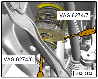
- The tensioner thrust plates must not contact the transverse link when tensioning the coil springs. Turn the thrust plates if necessary.
-- Tension the coil spring with the :VAS6274/6 by counterholding with the :VAS6274/7 .
Risk of injury due to uneven tensioning of the coil springs.
- The coil spring tension may only be released in the :VAS6274/9 .
-- Tension the coil spring until it can be removed.
-- If necessary for subsequent work, remove the :VAS6274/8 with :VAS6274/12-5 .
Release the coil spring tension in the :VAS6274/9 .
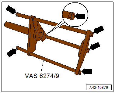
Loose threaded connections increase the risk of injury.
- Make sure the nuts -arrows- are secure and tighten if necessary before using the : VAS6274/9 .
-- Mount the :VAS6274/12-3 on the :VAS6274/9 .
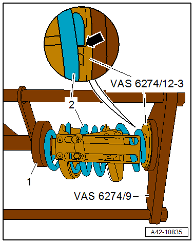
-- Place the pretensioned coil spring -2- with the bottom side on the spring support.
- The end of the spring coil must rest on the spring support stop -arrow-.
-- Guide the hydraulic tensioner plunger -1- out all the way to the coil spring and do not tighten.
-- Mark the plunger position -1- on the :VAS6274/9 -arrow A- with a waterproof felt-tip pen, for example.
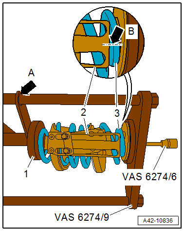
-- Mark the position of the anti-twist mechanism -2- on the coil spring -3- -arrow B- with a waterproof felt-tip pen, for example.
The marks are needed when tightening for installation.
There is a risk of damaging the threads.
- The :VAS6274/3 must not be tensioned or released using an impact wrench.
- Always turn the spindle using a commercially available ratchet.
-- Release the coil spring tension completely using the :VAS6274/6 with the hydraulic tensioner.
-- After the coil spring -1- tension is released, remove the :VAS6274/3 .
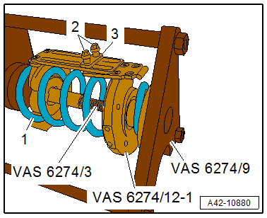
-- Remove the locking device bolts -2- and remove with the backing plate -3-.
-- Remove the :VAS6274/12-1 .
-- Press the locking plate -1- outward in the direction of the -arrow B- (open).
-- Remove the :VAS6274/12-7 with the :VAS6274/5 from the :VAS6274/12-2 .
-- Remove the thrust plate from the coil spring -2-.
Ignore items -3, 4 and arrow A-.
If the opposite coil spring in the vehicle should also be removed, then the installation position and attachment point of the locking device bracket to the thrust plates must be marked for later installation.
If the coil spring is replaced, then the applied mark must be transferred to the new coil spring.