Overview - Drive Axle: Notes
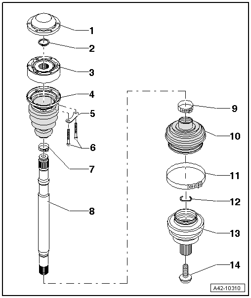
- Cap
- Always replace if damaged
- Carefully drive off using a drift
- Adhesive surface must be free of oil and grease
- Coat the sealing surface with Sealant :D 454 300 A2 before installing on CV joint. Refer to Inner CV Joint, Installing .
- Circlip
- Always replace after removing
- Insert in shaft groove
- Inner CV Joint
- Only replace completely
- Checking using the Vehicle Diagnostic Tester. Refer to INNER CV JOINT, CHECKING .
- Grease quantity and type. Refer to Grease Quantity and Type .
- The adhesive surfaces must be free of oil and grease.
- When installing the CV joint, thinly coat the profile shaft splines with the grease used in the joint.
- CV Boot
- Without vent hole
- Remove the cap carefully using a drift.
- Check for tears and scuffing
- Check the inner CV joint for damage. Refer to INNER CV JOINT, CHECKING .
- The metal cap/CV joint sealing surfaces must be free of grease when installing.
- Backing Plate
- Bolts
- M8: 30 Nm +90°
- M10: 50 Nm + 90°
- Always replace after removing
- Clamp
- Always replace after removing
- Tensioning. Refer to Fig 4.
- Drive Axle
- Removing and installing. Refer to DRIVE AXLE, REMOVING AND INSTALLING .
- Clamp
- Always replace after removing
- Tensioning. Refer to Fig 4.
- CV Boot
- Without vent hole
- Check for tears and scuffing
- Check the outer CV joint for damage. Refer to OUTER CV JOINT, CHECKING .
- The outer CV boot/metal cap sealing surfaces must be free of grease when installing
- The CV boot/drive axle sealing surfaces must be free of grease when installing
- Clamp
- Always replace after removing
- Tensioning. Refer to Fig 4.
- Circlip
- Always replace after removing
- Insert into ring groove of shaft before installation (not visible on installed joint)
- Before installing the CV joint, align the circlip centered to the opening facing upward.
- Outer CV Joint
- Only replace completely
- Checking using the Vehicle Diagnostic Tester. Refer to OUTER CV JOINT, CHECKING .
- Removing. Refer to DRIVE AXLE, DISASSEMBLING AND ASSEMBLING, OUTER CV JOINT .
- Installing: Drive onto shaft with a plastic mallet until compressed circlip rebounds.
- Circlip must lie in joint chamfer when guiding in, guide with pliers if necessary.
- Grease quantity and type. Refer to Grease Quantity and Type .
- The CV boot/outer CV joint sealing surfaces must be free of grease when installing.
- When installing the CV joint, thinly coat the profile shaft splines with the grease used in the joint.
- Bolt
- Always replace after removing
- Clean the threads in the CV joint with a thread tap.
- Drive axle threaded connection, loosening and tightening. Refer to DRIVE AXLE THREADED CONNECTION, LOOSENING AND TIGHTENING .
Heat Shield - Tightening Specification
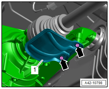
Version 1
-- Tighten the bolts -arrows- for the heat shield -1- to 23 Nm.
Version 2
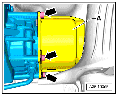
-- Tighten the bolts -arrows- for the heat shield -A- to 23 Nm.
Tension the Clamp Using the VAG1682A.
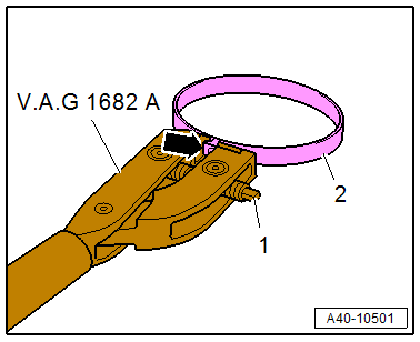
-- Attach the :VAG1682 as shown.
- The jaws on the pliers must be centered -arrow- on the clamp -2-.
NOTE:
The spindle threads must turn easily. If necessary, coat with MoS2 lubricating grease.
If difficult to tighten, for example because of dirty threads, the proper clamping force of the clamping sleeve will not be reached even when tightened to the specification.
-- Tension the clamp by turning the spindle -1- with the torque wrench. Do not tilt the clamping pliers during this.
- Tightening specification: 20 Nm.