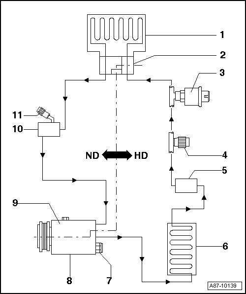
Refrigerant Circuit With Expansion Valve
Applies to vehicles with an Electrical A/C Compressor -V470- only with restrictions.
HP- High pressure side of refrigerant circuit.
LP- Low pressure side of refrigerant circuit.
| Component | Aggregate State of Refrigerant | Pressure (positive pressure) | Temperature | ||||
|---|---|---|---|---|---|---|---|
| -1- Evaporator, from input to output | Vapor | approximately 1.2 bar (17 psi)(1)1 | approximately -7 °C (-19.4 °F)(2)2 | ||||
| -2- Expansion valve | Fluid, released as vapor | approximately 14 bar (203 psi) | approximately 55 °C (131 °F) HP- side, reduces to -7 °C (-19.4 °F) LP-side | ||||
| -3- High pressure switch/high pressure sensor | Fluid | approximately 14 bar (203 psi) | approximately 55 °C (131 °F) | ||||
| -4- HP-side service connection and -5- Receiver/dryer | Fluid | approximately 14 bar (203 psi) | approximately 55 °C (131 °F) | ||||
| -6- Condenser | From gas (at input) via vapor to fluid (at outlet) | approximately 14 bar (203 psi) | From approximately 65 °C (149 °F) at input to approximately 55 °C (131 °F) at outlet | ||||
| -7- Pressure relief valve and -8- A/C compressor, HP-side | Gas | approximately 14 bar (203 psi) | approximately 65 °C (149 °F) | ||||
| -9- A/C compressor low pressure side | Gas | approximately 1.2 bar (17 psi)(1)1 | approximately -1 °C (30 °F)(2)2 | ||||
| -10- Pre-volume (not present in all vehicles) and -11- LP-side service connection | Gas | approximately 1.2 bar (17 psi)(1)1 | approximately -1 °C (30 °F)(2)2 | ||||
|
|||||||
A/C compressors which do not regulate their performance are switched off by the respective control module via the A/C Compressor Regulator Valve -N280- at an evaporator temperature below 0 °C (32 °F).
In vehicles with A/C Compressor Regulator Valve -N280-, the pressure is modified on the low pressure side by the valve.
Temperature and pressure in the refrigerant circuit in vehicles with two evaporators and two expansion valves correspond to those in vehicles with only one evaporator and one expansion valve (parallel switching).
Depending on the version of the refrigerant circuit, a component with an inner heat exchanger may be installed (for example, on the Audi A4 from MY 2008 and on the Audi A5 Coupe from MY 2008, a refrigerant line with an inner heat exchanger). Inside the inner heat exchanger, the flowing fluid warm refrigerant on the high pressure side is delivered into the low pressure side as flowing, vapor, cold refrigerant to increase the efficiency of the A/C system. Refer to REFRIGERANT LINE WITH INNER HEAT EXCHANGER .
Arrows point in direction of refrigerant flow.
HP- High pressure side of refrigerant circuit.
LP- Low pressure side of refrigerant circuit.
 Courtesy of AUDI OF AMERICA, LLC
- Evaporator
- Expansion Valve
- High Pressure Switch/High Pressure Sensor
- Different versions depending on vehicle
- Service Connection, HP Side
- Receiver/Dryer
- Different versions depending on vehicle
- Condenser
- Pressure Relief Valve
- A/C Compressor, HP side
- A/C Compressor, LP side
- Pre-Volumes
- Not present on all vehicles
- Service Connection, LP Side