Overview - Brake Booster/Brake Master Cylinder
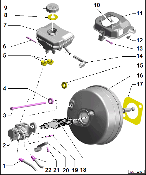
- Brake Line
- 14 Nm
- Brake master cylinder/secondary piston circuit to hydraulic unit
- Master Brake Cylinder
- Replace completely if faulty
- Refer to BRAKE MASTER CYLINDER, REMOVING AND INSTALLING
- Bolt
- 25 Nm
Replace damaged bolts and nuts.
Always replace the self-locking nuts and bolts.
Clean the bolts and nuts before reusing.
- 25 Nm
- Nut
- 23 Nm
- Replace after removing.
Always replace the self-locking nuts and bolts.
Replace damaged bolts and nuts.
Clean the bolts and nuts before reusing.
- Plugs
- To install, coat with brake fluid
- Locking Pin
- 8 Nm
- The locking pin must go through the brake fluid reservoir tabs.
- The locking pin must go through the brake master cylinder.
- The locking pin must be tightened.
- 8 Nm
- Brake Fluid Reservoir
- Fill pressure maximum 6 bar (87 psi).
- The locking pin must go through the brake fluid reservoir tabs.
- The locking pin must go through the brake master cylinder.
- The locking pin must be tightened.
- Refer to BRAKE FLUID RESERVOIR, REMOVING AND INSTALLING
- Fill pressure maximum 6 bar (87 psi).
- Seal
- Replace if damaged
- Cap
- Rubber Buffer
- Protective Plate
- Equipped on some models
- Rubber Buffer
- Bolt
- 8 Nm
- Brake Fluid Level Warning Switch -F34-
- Seal
- Replace after removing.
- Brake Booster
Always replace the self-locking nuts and bolts.
Replace damaged bolts and nuts.
Clean the bolts and nuts before reusing.
- Function Test:
-- With the engine switched off, press the brake pedal firmly several times (to reduce the vacuum in the device).
-- Hold the brake pedal with average foot pressure and start the engine. If the brake booster is working properly, the brake pedal will be felt to give noticeably under foot (booster becomes effective).
- Refer to BRAKE BOOSTER, REMOVING AND INSTALLING
- Adjust the ball head. Refer to Fig 2.
- Function Test:
- Seal
- Replace after removing.
- Push Rod
- The pushrod is only loosely inserted into the brake master cylinder and can fall into the brake booster when removing
- Actuator Pin
- For the Brake Lamp Switch -F-
- The actuator pin only functions for the brake lamp, not for the brake system
- If the pin is missing or is damaged, the brake lamp will not function
- Must not fall in the brake booster when removing the brake master cylinder.
- It must always be pushed into the hole in the brake master cylinder directly on the Brake Lamp Switch -F-
- Do not bend it
- Cannot be replaced separately
- Brake Lamp Switch -F-
- Bolt
- 8 Nm
- The brake lamp switch must be flush with the outer edge of the mount
- Brake Line
- 16 Nm
- Brake master cylinder/primary piston circuit to hydraulic unit
Adjusting the Brake Booster Ball Head
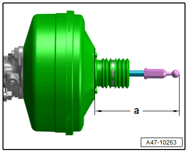
Risk of overheating the brakes due to the incorrect positioning of the actuator rod.
- Before installing the brake booster, adjust the actuator rod length with the ball head to the correct dimension.
- Dimension -a- = 164.7 mm ± 0.5 mm
- When measuring, the ball head must be aligned at a right angle to the brake booster surface.
- Measure to end of ball head without the seal.
Tightening Specifications
| Component | Nm | |
|---|---|---|
| Ball head to brake booster | 30 | |