Engine And Transmission, Separating, All Models Without High-Voltage System Except AUDI Q7/Q8
Special tools and workshop equipment required
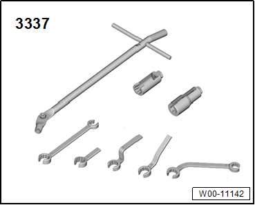
- Ring Wrench 7-Piece Set: 3337
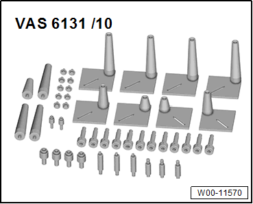
- Scissor Lift Table - Audi Set: VAS6131/10
- Scissor Lift Table - A8 Set - Adapter: VAS6131/11-2 from the Scissor Lift Table - A8 Set: VAS6131/11 , not illustrated
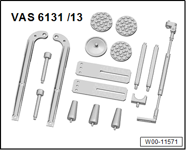
- Articulated Joint Support: 6131/13-7 from the Scissor Lift Table - Q7 Set: VAS6131/13
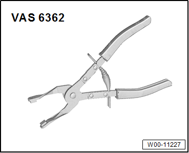
- Hose Clip Pliers: VAS6362
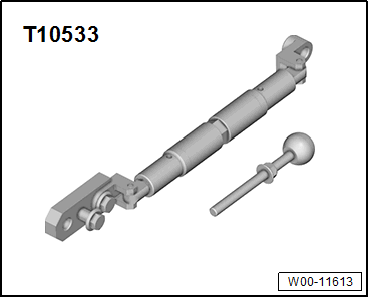
- Engine Support: T10533
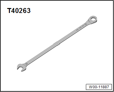
- Wrench - 21mm: T40263
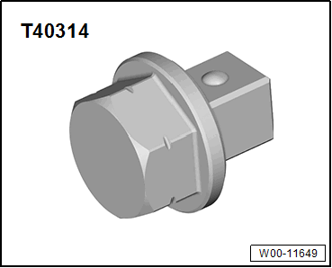
- Adapter: T40314
- 24 mm Socket
- Protective Eyewear
- Safety Gloves
- M12 nut, quantity: 2
Procedure
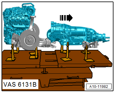
- Engine/transmission assembly removed and placed on the Scissor Lift Table: VAS6131B .
- During installation, all heat shield boots must be installed at the same location.
Vehicles with a Particulate Filter:
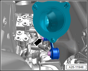
-- Remove the bolt -arrow- from the particulate filter bracket.
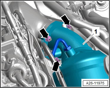
Risk of injury due to flying soot particles.
Irritation and injury to skin and eyes possible.
- Wear protective eyewear.
- Wear safety gloves.
-- Remove the nuts -arrows- and remove the particulate filter -1-.
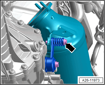
-- Remove the bolt -arrow- from the catalytic converter bracket.
Audi A6/A7:
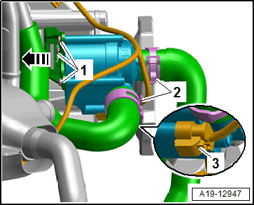
-- Remove the heat shield boot.
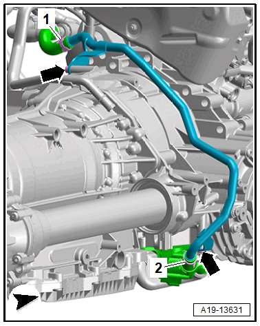
-- Disconnect the connector -3-.
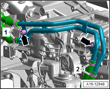
-- Release the retainer -arrow- and remove the After-Run Coolant Pump -V51- upward from the bracket.
-- Remove the bolts -arrows-, loosen the hose clamps -2-, and move the coolant pipes to the side.
Audi A6/A7, without Parking Heater:
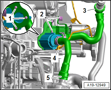
-- Remove the heat shield boot.
-- Disconnect the connector -4- for the Coolant Recirculation Pump -V50-.
-- Place a cloth underneath to catch leaking coolant.
-- Lift the clamps -3 and 5- and remove the coolant hoses.
Continuation for All Other Audi A6/A7:
-- Remove the bolts -2- and remove the bracket.
Audi A4/A5/A6/A7:
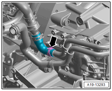
-- Place a cloth underneath to catch leaking coolant.
-- Loosen the hose clamp -arrow- and remove the coolant hose.
Audi A8:
-- Remove the ATF cooler. Refer to the appropriate Service Information .
-- Remove the ribbed belt tensioner. Refer to RIBBED BELT TENSIONER, REMOVING AND INSTALLING .
-- Remove the left transmission mount. Refer to the appropriate Service Information .
-- Lift the clamp -1- and remove the coolant hose.
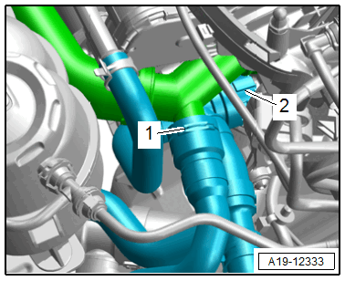
-- Loosen the hose clamp -1- and remove the coolant hose.
-- Remove the bolts -arrows- and push the right coolant pipe on the transmission to the side.
Continuation for All Vehicles:
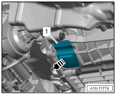
-- Remove the lower cover -1- from the transmission in direction of -arrow-.
-- To do so, use the Wrench - 21mm: T40263 , Adapter: T40314 and 24 mm socket to counterhold the crankshaft at the vibration damper.

Risk of damaging the engine by the timing mechanism skipping.
- Only let the engine turn in the direction of engine rotation.
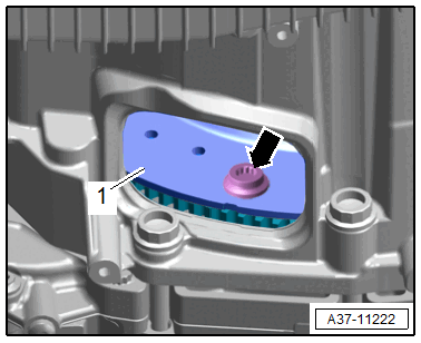
-- Remove the three bolts -arrow- on the drive plate -1-. Turn the crankshaft an additional 120° in the direction of engine rotation.
All Except Audi A8:
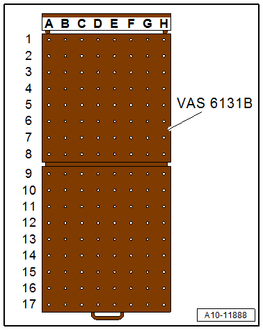
-- Equip the Scissor Lift Table: VAS6131B as follows:
- The remaining mounting elements remain unchanged.
| Table Coordinates | Components from the Scissor Lift Table - Audi Set: VAS6131/10 , Scissor Lift Table - A8 Set - Adapter: VAS6131/11-2 , Scissor Lift Table - Q7 Set - Articulated Joint Support: VAS6131/13-7 and the Engine Support: T10533/5 | |||
|---|---|---|---|---|
| D4 | Scissor Lift Table - Q7 Set - Articulated Joint Support: VAS6131/13-7 with Engine Support: T10533/5 | |||
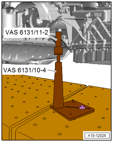
| C10 | /10-1 | /10-4 | /10-5 | /11-2 |
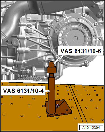
| F10 | /10-1 | /10-4 | /10-5 | /10-6 |
-- Tighten the Scissor Lift Table - Q7 Set - Articulated Joint Support: VAS6131/13-7 using two M12 nuts -arrow- and with the Engine Support: T10533/5 on the right side of the engine as shown.
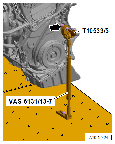
-- Tighten the engine support to the Scissor Lift Table: VAS6131B to 20 Nm.
-- Position the mounting elements from the Scissor Lift Table - Audi Set: VAS6131/10 and Scissor Lift Table - Audi Set - Adapter : VAS6131/11-2 on the left side of the transmission as shown.
-- Place the mounting element from the Scissor Lift Table - Audi Set: VAS6131/10 as shown on the right side of the transmission.
-- Turn the left and right spindles upward until all the mounting pins come into contact with the mounting points.
-- Tighten the mounting element base plates to 20 Nm on the Scissor Lift Table: VAS6131B .
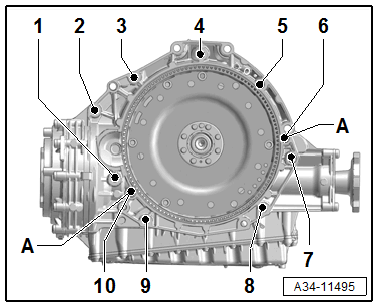
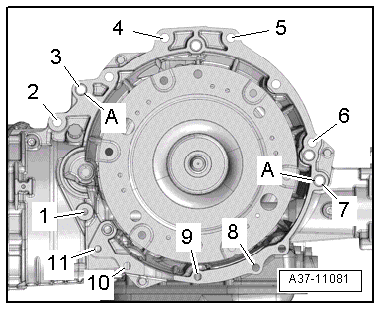
-- Remove the bolts -1 through 10- that connect the engine to the transmission.
 Courtesy of AUDI OF AMERICA, LLC
Audi A8:
-- Equip the Scissor Lift Table: VAS6131B as follows:
- The remaining mounting elements remain unchanged.
| Table Coordinates | Components from the Scissor Lift Table - Audi Set: VAS6131/10 , Scissor Lift Table - A8 Set - Adapter: VAS6131/11-2 , Scissor Lift Table - Q7 Set - Articulated Joint Support: VAS6131/13-7 and the Engine Support: T10533/5 | |||
|---|---|---|---|---|
| D4 | Scissor Lift Table - Q7 Set - Articulated Joint Support: VAS6131/13-7 with Engine Support: T10533/5 | |||
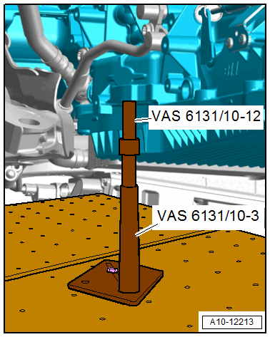
| C10 | /10-1 | /10-3 | /10-5 | /10-12 |
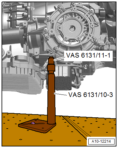
| F10 | /10-1 | /10-3 | /10-5 | /11-1 |
-- Tighten the Scissor Lift Table - Q7 Set - Articulated Joint Support: VAS6131/13-7 using two M12 nuts -arrow- and with the Engine Support: T10533/5 on the right side of the engine as shown.
-- Tighten the engine support to the Scissor Lift Table: VAS6131B to 20 Nm.
-- Place the mounting element from the Scissor Lift Table - Audi Set: VAS6131/10 as shown on the left side of the transmission.
-- Position the mounting elements from the Scissor Lift Table - Audi Set: VAS6131/10 and Adapter : VAS6131/11-1 on the right side of the transmission as shown.
-- Turn the left and right spindles upward until all the mounting pins come into contact with the mounting points.
-- Tighten the mounting element base plates to 20 Nm on the Scissor Lift Table: VAS6131B .
-- Remove the bolts -1 through 11- that connect the engine to the transmission.
Continuation for All Vehicles:
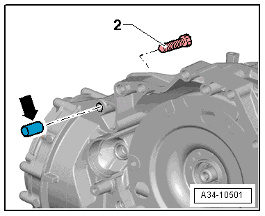
- The bolt -2- attaches the starter to the transmission and has an additional spacer sleeve -arrow-.
- Remove this spacer sleeve when removing the upper starter bolt.
-- Loosen the clamping screw on the sides of the Scissor Lift Table: VAS6131B slightly pull back the rear table top with the transmission -arrow-, at the same time slightly tilt forward the engine using the Scissor Lift Table - Q7 Set - Articulated Joint Support: VAS6131/13-7 .