Overview - Camshaft Timing Chains
WARNING: This page is about a different variant/trim than selected.
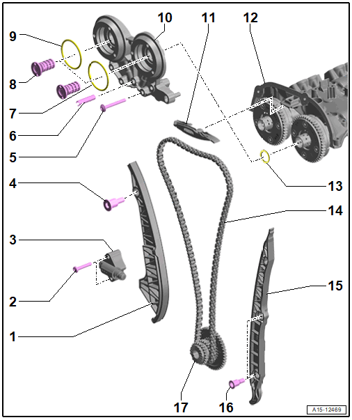
- Tensioning Rail
- For the camshaft timing chain
- Bolt
- 9 Nm
- Chain Tensioner
- Is under tension
- Secure with the Locking Tool: T40435 before removing
- Guide Pin
- 20 Nm
- Bolt
- Replace after removing
- Tightening sequence. Refer to Fig 2.
- Adapter Sleeve
- Pulled into the cylinder head with the bolt. Refer to Fig 2.
- O-Ring
- Replace after removing
- Installed depending on the performance class
- Lubricate with engine oil
- Control Valve
- 35 Nm
- Left-hand thread
- Check using the Vehicle Diagnostic Tester Refer to Fig 4.
- O-Ring
- Replace after removing
- Installed depending on the performance class
- Lubricate with engine oil
- Bearing Bracket
- Coat the holes, radial bearings and the axial bearings with engine oil.
- Removing and Installing. Refer to BEARING BRACKET, REMOVING AND INSTALLING .
- Guide Rail
- For the camshaft timing chain
- Cylinder Head Cover
- Spacer
- Camshaft Timing Chain
- Mark the running direction with paint for reinstallation
- Removing and Installing. Refer to CAMSHAFT TIMING CHAIN, REMOVING AND INSTALLING .
- After working on the chain drive, the adaptation must be performed using the Vehicle Diagnostic Tester Refer to PERFORM ADAPTATIONS AFTER COMPONENT REPLACEMENT .
- Guide Rail
- For the camshaft timing chain
- Guide Pin
- 20 Nm
- Three Stage Chain Sprocket
- Installation position. Refer to Fig 3.
Bearing Bracket - Tightening Specifications and Sequence
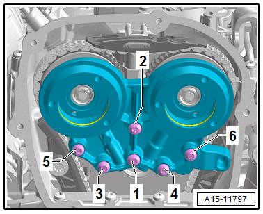
If an adapter sleeve is installed, this will be moved with the bolt -1- in the cylinder head.
-- Tighten the bolts in the steps in the sequence shown:
| Step | Bolts | Tightening Specification |
|---|---|---|
| 1. | -1- | 3 Nm (adapter sleeve, installing) |
| 2. | -1 to 6- | 9 Nm |
Three Stage Chain Sprocket - Installed Position
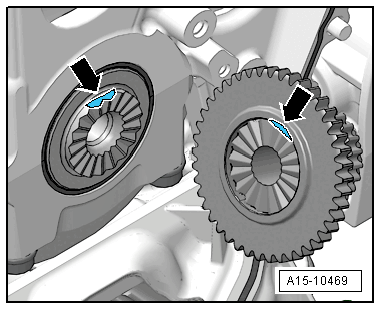
- Both surfaces -arrows- must align.
Checking the Control Valve
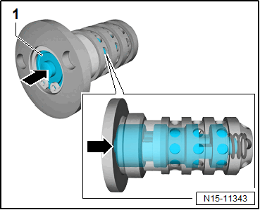
- The piston -1- must be pushed in approximately 3 mm against the spring force. It must not become stuck while doing so.