Overview - Cylinder Head
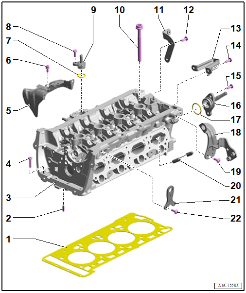
- Cylinder Head Gasket
- Replacing. Refer to CYLINDER HEAD, REMOVING AND INSTALLING .
- Installed position: the part number faces the cylinder head
- After replacing an adaptation must be preformed. Refer to PERFORM ADAPTATIONS AFTER COMPONENT REPLACEMENT .
- Alignment Pin
- Quantity: 2
- Cylinder Head
- Removing and Installing. Refer to CYLINDER HEAD, REMOVING AND INSTALLING .
- Checking for distortion. Refer to Fig 7.
- Pay attention to the cylinder head cover pairing number and cylinder head. Refer to Fig 4.
- Change the coolant and engine oil after removing and installing
- After removing and installing or replacing an adaptation must be performed. Refer to PERFORM ADAPTATIONS AFTER COMPONENT REPLACEMENT .
- Cap installation and installation position. Refer to Fig 8.
- Bolt
- Heat Shield
- Bolt
- 9 Nm
- O-Ring
- Replace after removing
- Coat with coolant
- Bolt
- 9 Nm
- Connection
- For coolant hose
- Bolt
- Bracket
- Bolt
- 9 Nm
- Bracket
- Bolt
- 9 Nm
- Bolt
- 9 Nm
- Connection
- For coolant hose
- O-Ring
- Replace after removing
- Coat with coolant
- Engine Lifting Eye
- Bolt
- 10 Nm +90°
- Replace after removing
- Partition Plate
- Engine Lifting Eye
- Bolt
- 10 Nm +90°
- Replace after removing
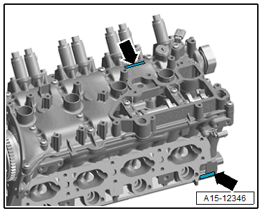
Loosening the Cylinder Head
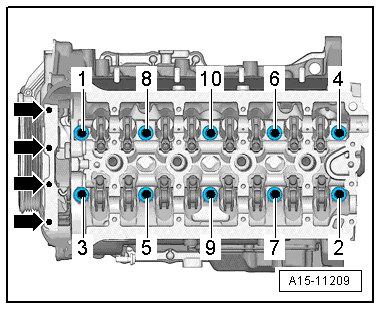
-- Remove the bolts -arrows-.
-- Loosen and remove the cylinder head bolts in the sequence -1 to 10-.
Cylinder Head - Tightening Specifications and Sequence
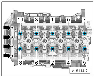
- Replace bolts that were tightened with an additional turn after removing them.
-- Tighten the bolts in the steps in the sequence shown:
| Step | Bolts | Tightening Specification/Additional Turn |
|---|---|---|
| 1. | -1 through 10- | Install all the way by hand |
| 2. | -1 through 10- | 50 Nm |
| 3. | -1 through 10- | 90° additional turn |
| 4. | -1 through 10- | 90° additional turn |
| 5. | -arrows- | 8 Nm |
| 6. | -arrows- | 90° additional turn |
Pairing Number of the Cylinder Head Cover and the Cylinder Head
 Courtesy of AUDI OF AMERICA, LLC
Each cylinder head cover is assigned to a cylinder head with this pairing number.
- Both eight digit numbers -arrows- must match: XXXXXXXX = XXXXXXXX.
- For the assembly pay attention to the correct allocation.
Heat Shield - Tightening Specification
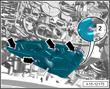
-- Tighten the nuts -arrows- and bolt -2- to 9 Nm.
Heat Shield Lower Bracket - Tightening Specification
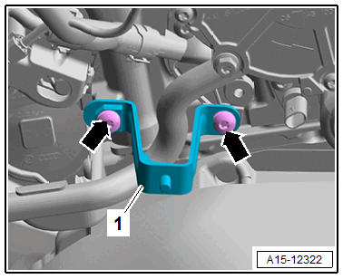
-- Tighten the bolt -arrows- to 9 Nm.
Cylinder Head, Checking for Distortion
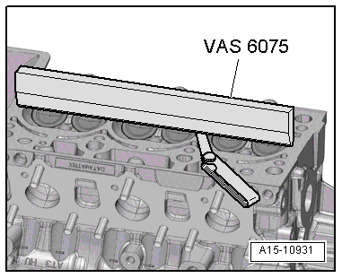
-- Check the cylinder head at several locations for distortion using a Straight Edge - 500mm: VAS6075 and a feeler gauge.
- Maximum permitted distortion: 0.05 mm
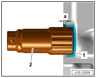
Cap Installation and Installation Position
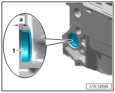
-- Before removing, determine the press-in depth -a-.
-- Coat the cap -1- all around with sealant. Refer to Electronic Parts Information (ETKA).
-- Position the cap -1- parallel to the cylinder block and using a suitable thrust piece (for example the socket) -2- drive in to the previously determined press-in depth -a-.