Overview - Cylinder Block, Belt Pulley Side, Vehicle With Generator
WARNING: This page is about a different variant/trim than selected.
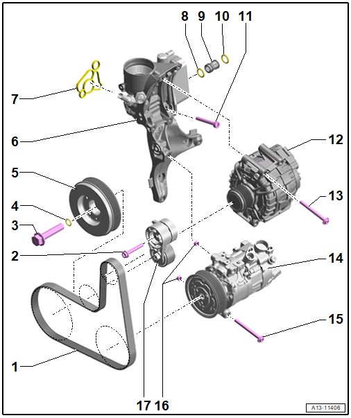
- Ribbed Belt
- Check for wear
- Do not kink
- Ribbed belt routing. Refer to Fig 2.
- Before removing, mark the running direction using chalk or a felt-tip pen.
- Removing and Installing. Refer to RIBBED BELT, REMOVING AND INSTALLING, VEHICLE WITH GENERATOR .
- When installing, make sure it is seated correctly on the ribbed belt pulleys
- Bolt
- 20 Nm +90°
- Replace after removing
- Bolt
- 100 Nm +180°
- Replace after removing
- O-Ring
- Included in a delivery package -item : Bolt; cannot be delivered separately
- Vibration Damper
- With the ribbed belt pulley
- Removing and Installing. Refer to VIBRATION DAMPER, REMOVING AND INSTALLING .
- Sub-Assembly Bracket
- With oil filter housing and engine oil cooler
- Removing and installing the sub-assembly bracket. Refer to SUB-ASSEMBLY BRACKET, REMOVING AND INSTALLING .
- Removing and installing the engine oil cooler. Refer to ENGINE OIL COOLER, REMOVING AND INSTALLING .
- Seal
- Replace after removing
- O-Ring
- Replace after removing
- Coat with coolant
- Connection
- O-Ring
- Replace after removing
- Coat with coolant
- Bolt
- Replace after removing
- Tightening Specifications and Sequence. Refer to Fig 3.
- Generator
- Overview. Refer to OVERVIEW - GENERATOR .
- Bolt
- Tightening specification. Refer to OVERVIEW - GENERATOR .
- A/C Compressor
- Removing and Installing. Refer to A/C COMPRESSOR, REMOVING AND INSTALLING FROM BRACKET .
- Bolt
- Tightening specification. Refer to OVERVIEW - A/C COMPRESSOR .
- Alignment Sleeves
- Tensioner
- For the ribbed belt
- Removing and Installing. Refer to RIBBED BELT TENSIONING DAMPER, REMOVING AND INSTALLING, VEHICLE WITH GENERATOR .
Ribbed Belt Routing - Generator
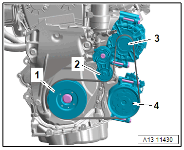
- Vibration Damper
- Ribbed Belt Tensioner
- Generator
- A/C Compressor
Sub-Assembly Bracket - Tightening Specifications and Sequence
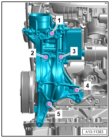
- Replace bolts that were tightened with an additional turn after removing them.
-- Mount the sub-assembly bracket and then install the bolts -4- first.
-- Tighten the bolts -1 to 5- in stages in the sequence shown.
| Step | Tightening Specification/Additional Turn |
|---|---|
| 1. | Install all the way by hand |
| 2. | 20 Nm |
| 3. | 90° additional turn |
Vibration Damper - Versions
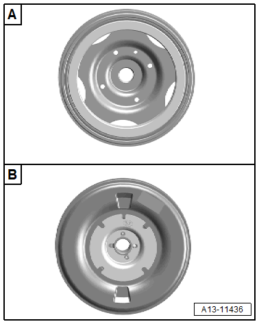
A -
Version 1 (different versions)
- If the fan shroud is installed use the Wrench - 21mm: T40263 , Adapter: T40314 and the Wrench - 24mm to turn.
- Use the Counterhold: T40378 to counterhold.
B -
Version 2
- If the fan shroud is installed use the Offset Open-End Wrench - 24mm to turn.
- Use the Counterhold: T40379 to counterhold.