Camshaft, Removing And Installing: Installing
- The crankshaft must not be at "TDC".
- Replace bolts that were tightened with an additional turn after removing them.
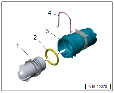
- Check the O-ring in the Crankcase Pressure Sensor -G1068- for damage. Refer to OVERVIEW - CRANKCASE VENTILATION .
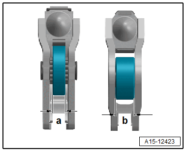
-- If removed, install the roller rocker lever and the hydraulic lifter as instructed by the markings. Refer to Figure.
-- Make sure all the roller rocker levers lie correctly on the ends of the valve stems and are clipped onto the respective hydraulic lifters.
In the case that the crankshaft has been turned in the meantime:
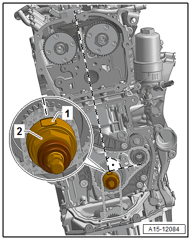
-- Turn the crankshaft on the hex fitting -2- to "TDC" point.
- In "TDC" point the flattened position -1- is in an imaginary vertical line between the camshaft chain sprockets.
-- Then turn the crankshaft 90° counter-clockwise out of "TDC".
-- Cover the open engine components with a clean cloth.
Risk of injuring the eyes from sealant residue.
- Wear protective eyewear.
-- Remove the sealant residues at the cylinder head using a blade scraper (width at least 40 mm).
-- Remove any sealant residue from the groove on the cylinder head cover as well as on the sealing surfaces.
-- Clean any oil or grease off the sealing surfaces.
-- Bring the pin of the cam adjustment actuator into the installation position. Refer to Installing .
-- Coat the camshaft contact surfaces with engine oil.
-- Remove the : T40271/1 and : T40271/2 from the cylinder head -arrows-.
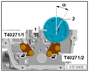
-- Insert the intake camshaft -1- in the cylinder head and align with the marking -2-.
- Angle α = 30°.
- The cam lobes of cylinder 4 point upward.
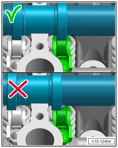
-- Align the intake camshaft centrally to the roller rocker lever.
Risk of injuring the eyes due to the sliding bar ball springing out.
- Wear protective eyewear.
-- Insert the intake camshaft in the cylinder head cover.
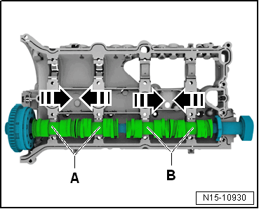
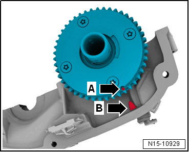
- The cam pair -A and B- must be pushed together.
-- Turn the exhaust camshaft until the markings -A and B- align.
Risk of engine damage due to excess sealant in the lubrication system.
- Do not apply sealant bead thicker than indicated.
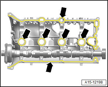
-- Apply sealant to the clean sealing surfaces of the cylinder head cover -arrows- as shown.
- Sealant bead thickness: 1.5 to 2.5 mm
-- Secure the camshaft and place the cylinder head cover with the camshaft on the cylinder head, at the same time pay attention to the alignment pins.
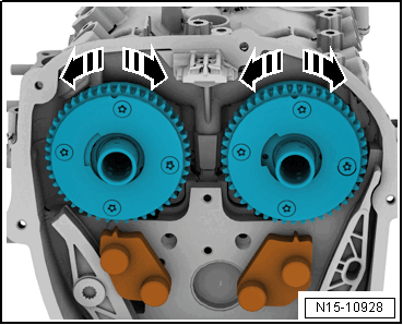
-- Lightly press on the cylinder head cover by hand and at the same time slightly push the camshafts back and forth in direction of -arrows- until the cylinder head cover lays on the cylinder head >>without tension<<.
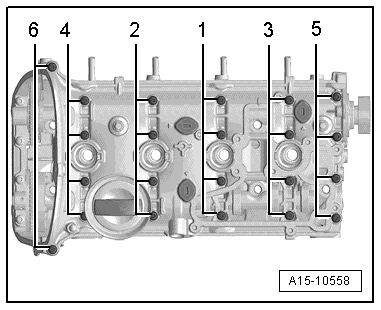
-- Tighten the bolts in multiple steps. Refer to Figure.
- Pay attention that the cylinder head cover is not tilted.
- Remove the excess sealant leaking from tightening.
-- Turn the intake camshaft with the : T40427 in the direction of -arrow B- until the marks -1 and 2- align.
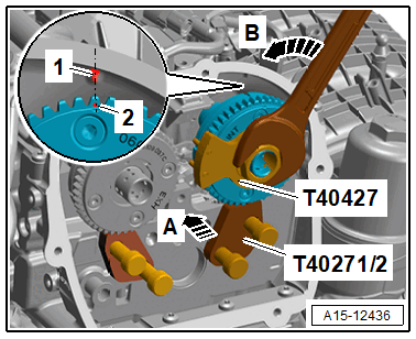
-- Push the : T40271/2 in the chain sprocket splines in direction of -arrow A-.
-- Turn the exhaust camshaft using the : T40427 in direction of -arrow B-, until the marking -2- of the exhaust camshaft is shifted by half a tooth clockwise to the marking -1- on the cylinder head cover.
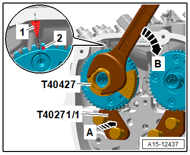
-- Push the : T40271/1 in the chain sprocket splines in direction of -arrow A-.
-- Turn the crankshaft on the hex fitting to the "TDC point".
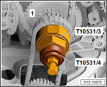
- The flattened surface -1- must be on top.
-- Remove the : T10531/4 and the : T10531/3 .
Install in reverse order of removal. Note the following:
- Secure all hose connections with hose clamps that match the ones used in series production. Refer to the Parts Information.
- Check the O-ring in the crankcase ventilation hose for damage. Refer to OVERVIEW - CRANKCASE VENTILATION .
-- Install the camshaft timing chain. Refer to CAMSHAFT TIMING CHAIN, REMOVING AND INSTALLING .
-- Install the vacuum pump. Refer to VACUUM PUMP, REMOVING AND INSTALLING .
-- Install the high pressure pump. Refer to HIGH PRESSURE PUMP, REMOVING AND INSTALLING .
-- Install the oil separator. Refer to OIL SEPARATOR, REMOVING AND INSTALLING .
-- Install the ignition coils. Refer to IGNITION COILS, REMOVING AND INSTALLING .
-- Install the upper timing chain cover. Refer to UPPER TIMING CHAIN COVER, REMOVING AND INSTALLING .
-- Connect the coolant hoses with the connector coupling. Refer to Fig 5.
-- Check the coolant level. Refer to COOLANT LEVEL, CHECKING AND FILLING .
-- Install the air filter housing. Refer to AIR FILTER HOUSING, REMOVING AND INSTALLING .
-- Install the engine cover. Refer to ENGINE COVER, REMOVING AND INSTALLING .
Risk of damaging the valves and piston crowns by performing procedures on the valvetrain.
- Only start the engine 30 minutes after installation of the camshaft so that they do not contact the hydraulic lifters.
- To ensure valves do not strike pistons when starting, carefully rotate the crankshaft at least two turns.