Overview - Crankshaft
WARNING: This page is about a different variant/trim than selected.
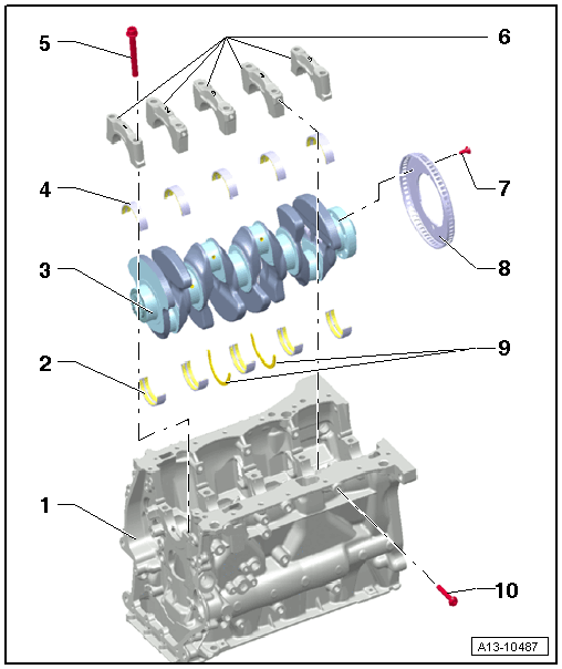
- Cylinder Block
- Cylinder Block Bearing Shell
- With oil groove
- Crankshaft bearing shells identification (classification). Refer to MAIN BEARING SHELLS ALLOCATION .
- Lubricate with engine oil
- Crankshaft
- For assembly work, secure the engine on the engine and transmission holder. Refer to ENGINE, SECURING TO ENGINE AND TRANSMISSION HOLDER .
- Removing and Installing. Refer to CRANKSHAFT, REMOVING AND INSTALLING .
- After removing, set it aside so that the sensor wheel -item ) Sensor Wheel is not rested on and becomes damaged
- If the crankshaft is being replaced, then the bearing shells must be reallocated to the bearing cap. Refer to MAIN BEARING SHELLS ALLOCATION .
- Axial play, measuring. Refer to CRANKSHAFT, MEASURING AXIAL CLEARANCE .
- Radial play, measuring. Refer to CRANKSHAFT, MEASURING RADIAL CLEARANCE .
- Crankshaft dimensions. Refer to CRANKSHAFT DIMENSIONS .
- Bearing Shell for Bearing Cap
- Without oil groove
- Crankshaft bearing shells identification (classification). Refer to MAIN BEARING SHELLS ALLOCATION .
- Lubricate with engine oil
- Bolt
- Tightening specification and sequence. Refer to Fig 2.
- Replace after removing
- Use old bolts for the radial clearance measurement
- Bearing Cap
- Bearing cap allocation. Refer to Fig 3.
- Bolt
- 10 Nm +90°
- Replace after removing
- Replace the sensor wheel -item ) Sensor Wheel every time the bolts are loosened. Refer to SENSOR WHEEL, REMOVING AND INSTALLING .
- Sensor Wheel
- For the Engine Speed Sensor -G28-
- Only possible to install in one position
- Replace the sensor wheel every time the bolts -item ) Bolt are loosened
- Removing and Installing. Refer to SENSOR WHEEL, REMOVING AND INSTALLING .
- After replacing an adaptation must be preformed. Refer to PERFORM ADAPTATIONS AFTER COMPONENT REPLACEMENT .
- Thrust Washers
- Lubricate with engine oil
- For bearing 3
- Bolt
- Tightening Specifications and Sequence. Refer to Fig 2.
- Replace after removing
Crankshaft - Tightening Specification and Sequence
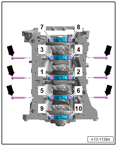
- Replace bolts that were tightened with an additional turn after removing them.
-- Tighten the bolts in the steps in the sequence shown:
| Step | Bolts | Tightening Specification/Additional Turn |
|---|---|---|
| 1. | -1 to 10- and -arrows- | Install all the way by hand |
| 2. | -1 through 10- | 65 Nm |
| 3. | -1 through 10- | 90° additional turn |
| 4. | -arrows- | 15 Nm |
| 5. | -arrows- | 90° additional turn |
Bearing Cap Allocation
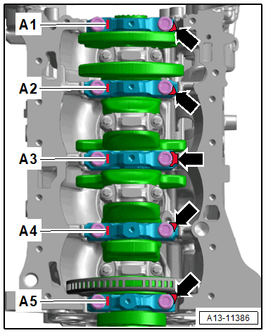
The bearing caps are marked to the cylinder block to prevent them from being incorrectly installed.
| Identification | Installation Position |
|---|---|
| A1 | Front |
| A2 | Front center |
| A3 | Center |
| A4 | Rear center |
| A5 | Rear |
- The tabs -arrows- on the bearing caps point toward the crankshaft bearing "3" on the intake side.